![]()
"Topology" can be used to describe the shape of a network. It is a term that should be used with care as its misuse can be misleading. The following discussion will describe physical topology simply to aid in the understanding of how different types of ethernet are implemented. Beyond the bus and star topologies mentioned below, the ring topology is discussed elsewhere, in terms of token ring.
Confusion can arise if a 10BaseT, or 100BaseT, network is described as having a star topology. These networks have a star physical topology, but they are bussed across the hub. Some texts prefer to avoid difficulties altogether by not discussing topologies at all.

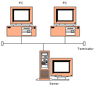
All network elements are connected to the same medium via a short cable. Data propagates along the medium in both directions from the transmitting device. Terminators are required, at the end of the bus, to prevent reflection of the signals across the media.
Buses are vulnerable to cable damage. If any part of the bus is damaged, the whole network grinds to a halt. Some network devices will be isolated from the rest of the network and any signal propagating across the bus will be distorted by the damage to the cable. Proper network documentation is always essential to aid in fault finding, but this is particularly the case in bussed installations. If an unknown device is transmitting masses of corrupt data, it may be difficult to identify which device is responsible and then isolate it.
Many bussed installations are legacies and are being superseded by 10BaseT and 100BaseT, but there are advantages to the bus - a relatively short length of media is required to connect all devices and they are a simple solution to the needs of distributed computing. CSMA/CD is used as the method of medium access control.
10Base5 installations use a viper tap to pierce the thick coaxial cable media that acts as the bus. The viper tap has a short length of thick coaxial that is used to connect the tap to the network interface card.
10Base2 installations use a BNC T-piece. The thin coaxial bus is cut and a T-piece used to join the two ends. The third connection on the T-piece is attached to a short cable, which, in turn, connects to the network interface card.

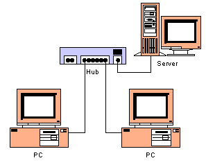
All devices on the segment are connected to a hub, this is analogous to a star shape with the hub at the centre and other devices radiating out from it. Each device has its own connection to the hub. The hub is, therefore, vital to the operation of the network. It is good practice to have upto twice as many hub ports as required. Should a port fail, the cable can simply be swapped to one of the spare ports. This is known as redundancy.
Both 10BaseT and 100BaseT use a star physical topology over unshielded twisted pair wire media.
Each device has its own link to the network, but star physical topologies
can still suffer from congestion. This is due to the broadcast nature of
ethernet - each station still uses CSMA/CD. Every broadcast from any device
propagates to all other devices in order to reach its intended destination.
This leads to unnecessary traffic that could overwhelm an already struggling
network. Switches can be used in the place of
hubs to manage traffic more effectively.
| Brian Brown's NT Networking Course | Marvellous networking site |
| Co-axial - Central Institute of Technology | Coaxial cable information |
| Twisted Pair - Central Institute of Technology | Twisted pair details |
| Wiring Guide - Central Institute of Technology | Wiring information |