
All About Microphones
On this page there is a section on vocabulary that describes and defines the parts
of a microphone. Having a clear vocabulary helps explain how one microphone differs
from another, and that in turn helps one understand at a fundamental level which
microphone might work better than another in a particular situation.
Following the section on vocabulary, there are three sections on qualities of a microphone
that represent a tradeoff. These are:
1.) The degree of miniaturization.
2.) The degree of directionality.
3.) The degree of audio fidelity.
Generally, optimizing one of the above qualities comes at the expense of the others.
Finally, there is a discussion of the underlying microphone technologies.
There are four technologies that one might encounter in house-of-worship
applications. They are:
1.) Dynamic microphones,
2.) Condenser microphones,
3.) Ribbon microphones,
4.) Piezoelectric or crystal microphones.
This discussion of microphones is written with house-of-worship applications in
mind. There are many other discussions of types of microphones that have greater
generality. Wikipedia's article on microphones is one example.
Vocabulary
Capsule
All microphones depend on some sort of analog
transducer that converts
the acoustic energy of sound waves into an electrical signal. More often in the
professional audio industry the transducer is called a capsule. But it may
sometimes be called a cap or a cartridge or a microphone element.
It will usually be called a capsule for these web pages. The capsule needs
to be mechanically protected so that the microphone can be handled without damaging
the capsule, and so that the capsule can be properly exposed to sound but screened
from wind and handling noise. This page is all about these capsules and the mechanical
housing and associated parts around the capsule.
Some capsules create more powerful electrical signals than others. Some capsules
create signals strong enough to directly pass through hundreds of feet of microphone
wire before they need any amplification. The most powerful capsules create so-called
microphone-level signals. These are voltage signals of about –40 dBV
down to about –60 dBV. (About 1 to 10 mV peak) That's not really very
strong! Other capsules create even weaker signals. They require a preamplifier to
be located adjacent to the capsule (inside the microphone) or within a few feet of
the capsule, say in a bodypack. There a preamplifier strengthens the signal to an
optimal level for sending down a cable or for wireless transmission. The preamplifier
in or near the microphone creates a so-called "line-level" signal that is even stronger
than a microphone-level signal. Line-level signals are in the range of about +1.8 dBV
down to about –10 dBV, with 0 dBV as nominal. (1228 mV down to 316 mV peak
with 1000 mV as nominal)
It is a little ironic that by the time the signal gets to the mixer board, the capsules
that generate the strongest signals ("mic level") provide the board with the weakest
signals ("mic level") due the absence of a preamplifier ahead of the mixer board.
But there is a minor advantage in the absence of a preamplifier. Each amplifier or
preamplifier in the pathway of the signal needs to be properly gain
structured. Improper gain structure causes noise or distortion. Capsules that
require no preamplification—mic-level capsules—avoid a potential gain
structure problem. Sometimes mic level capsules are preferred solely for this advantage.
Capsules that require a preamplifier must be properly gain structured. Some preamplifiers
have a switch or knob that can be adjusted to adapt the preamplifier to the audio loudness
the capsule is exposed to. Since gain structure is even more critical if a wireless
channel is employed, almost all wireless microphones have gain trim adjustments, which
may be hidden behind a battery door or deep on a menu. Most capsules that require a
preamplifier and are intended to be used in a wired channel have a factory-preset
gain trim which is not adjustable. If the audio loudness is too loud or too soft to
adequately match this pre-set gain trim setting, one has no other choice except to
substitute a different microphone type (different brand or model) that is a better
match to the situation.
Some microphones are available with a selection of different capsules that may be mounted
in or on them. Other microphones include two or more capsules with a switch to select
how the capsules are connected to the electrical output of the microphone. (The "Blue"
brand of microphones has made a sort of specialty of selling microphones with multiple
capsules. The "Blue Yeti" microphone and its variants have multiple capsules built in
and selectable by a switch. The "Blue Bottle" has a selection of optional capsules
than can be attached to the main housing of the microphone. But Blue is not the first
or only company to provide such offerings.) Even if a microphone has only one available
capsule, the capsule is usually a replaceable part if the microphone is carefully
disassembled.
Shock Mount
Most capsules are suspended inside a housing via a shock mount. Sometimes the
shock mount and the capsule are a single indivisible assembly. A shock mount is usually a rubber
assembly with some damping, arranged so that mechanical vibrations from handling
the microphone do not get mechanically coupled into the capsule and mixed with the audio.
Shock mounts can have varying degrees of sophistication or, in the case of inexpensive
microphones, might be rather ineffective or even entirely absent, with the capsule
mechanically fastened directly into the microphone housing.
Windscreen
It is desirable that only sound gets to the capsule, no wind or breath noise. There are
three types of wind-sounds to consider.
1) The ordinary breeze of the day, such as is reported in the weather forecast, needs to
be considered if the microphone is used outdoors. This breeze can cause turbulent air
flow over the capsule, which will create an obnoxious rustling sound. Almost certainly
the microphone's built-in windscreening will need to be supplemented.
2) There is also wind caused by the motion of the microphone. Suppose a microphone is
handheld and the vocalist is not singing, holding the microphone near a thigh in a
relaxed manner. Then the vocalist raises the microphone to sing. This type of motion
is equivalent to a breeze of about 10 to 15 MPH. If the vocalist is dancing or acting
in a theatrical manner this type of breeze can be even greater.
3) There are plosive sounds in
speech and singing. These produce puffs of air that are expelled from the vocalist's mouth but are usually inaudible
in daily life—until a microphone picks them up and emphasizes them. Most
microphones, if they are in just the wrong position, become sensitive to these plosives,
distorting the sound. The area of maximum plosive turbulence is usually about three inches
straight out from the mouth and a half-inch down. Hold the capsule of the microphone
almost anywhere else for a better sound! To mitigate these three sources of wind noise,
most microphones include some windscreening.
Because windscreening can muffle the sound, as if you are listening through a pillow,
windscreening built into a microphone is usually kept to a minimum. Ideally, vocalists
should be trained to avoid putting the microphone in the stream of plosives.
Only enough windscreening is usually provided for use outside the stream of plosives.
Optional external windscreens, often in the form of foam socks that cover the microphone,
sometimes in the form of a mesh disk suspended between the vocalist and the microphone,
can be used to add additional windscreening if desired.
Preamplifier
Some capsules develop such weak signals that a preamplifier must be located within inches,
sometimes even within millimeters, of the capsule. Other microphones do not need or
contain any preamplifier. A preamplifier can be smaller than a grain of rice or, especially
in older microphones, possibly a little larger than a 12 oz. can of pop. Microphones that
connect via USB always have an electronics package in them to manage the USB connection.
This electronics package might be labeled as a preamplifier even though it contains more
functionality than that.
Body
Also known as the handle, shell or case. This is the part of the
microphone that holds everything together. If the microphone is handheld, then this is
the part that is intended to be held.
Microphone
For the purpose of this tutorial, a microphone is the assembly of hardware that
consists of the capsule and, if necessary, the preamplifier, and the shock mounting,
and the housing around that and the windscreening to ideally allow only sound to reach
the capsule. A microphone might also contain various switches (e.g. on/off).
There will be a separate page in this tutorial on the electrical connection between
the microphone and the mixer board or wireless transmitter or PA amplifier. There
will also be a separate page on handling and using microphones.
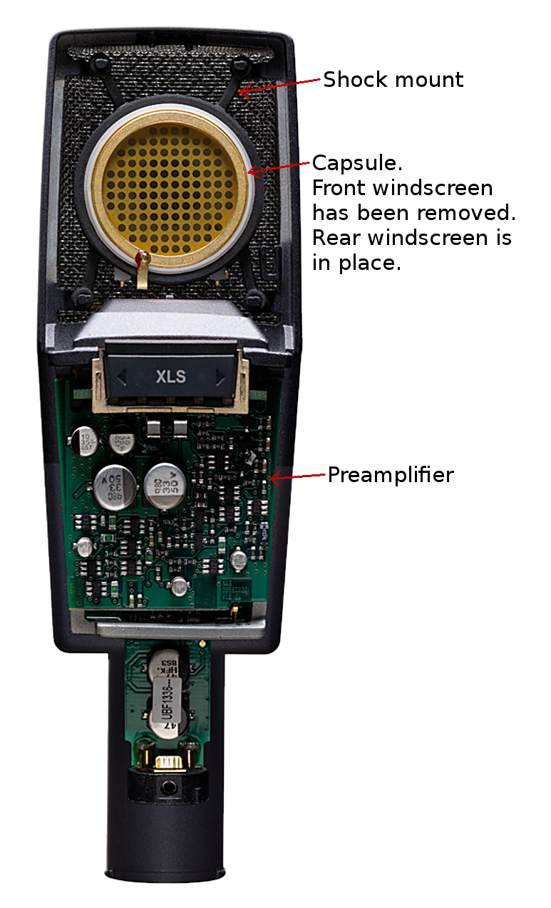
Above: A view of the inside of a typical studio microphone.
(AKG model C414 XLS )
Click on the photo for a higher resolution view.
Photo ©2018 by AKG.com, used with permission.
Three qualities that get traded-off
There are three characteristics of microphones that get traded-off. These are: Miniaturization, Directionality, and Audio Fidelity.
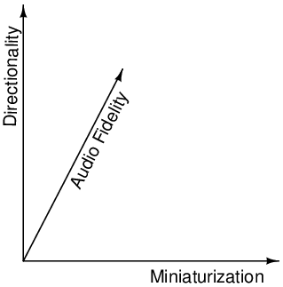
Above: A visualization of the placement of a microphone in a 3-D space based on
its characteristics.
Any given microphone can be visualized as occupying a place in a three-dimensional
space. As any one of the above gets optimized, it tends to come at the expense of one or
both of the other qualities listed above. For example, if you accept a very large microphone
(zero effort at miniaturization) that is sensitive to sound from all directions (no
directionality), then you can have very high audio fidelity. Or maybe you want a
very directional microphone. You can expect that to tend to be a large and low fidelity
microphone.
As effort is taken to optimize one of these three characteristics, and as the other
characteristics are traded away, the location of the microphone in this classification
system tends to move toward one of the two planes containing the axis being optimized,
or even near the axis itself. Down through the decades microphone designs have gotten
better and there are more options located far from the origin and away from the three planes
of optimization.
1.) Degree of miniaturization (vs. directionality and fidelity)
This category is about more than just physical size. It is also about
how easily the microphone can be handled and positioned. In the 1920's microphones were
large conical horns connected to metal pipes to route the acoustic energy to a
diaphragm mounted on a lathe to cut a recording directly with the acoustic energy
collected. It was anything but convenient to use one of these microphones.
Above: Two examples of early acoustic-powered microphones,
circa 1925. (click an image for a larger view)
One fact remains to this day. The essential problem with
miniaturization of a microphone is the declining amount of acoustic energy that
the microphone can obtain from the sound in the air as the microphone gets smaller.
In a studio environment larger and more awkward arrangements can be accepted.
In live-sound reinforcement miniaturization is especially valuable, and other
qualities can be sacrificed. With this type of trade-off in mind, the degree of
miniaturization needed will also be influenced by how the microphone needs to appear
(or disappear) or be mounted in the room. If a microphone is going to be hand-held,
it should not be so small as to be hard to hold without the use of tweezers! Market
experience shows that hand-held microphones sell best when they are about the size
of an ice-cream cone. The degree of miniaturization that is desirable is influenced
by the overall characteristics of the situation.
The discussion below starts with the largest present-day microphone styles (little
need for miniaturization) and proceeds toward the smallest microphone styles.
Studio-type microphones
These are the characteristics of a studio-type microphone:
- As big and heavy as needed for high-fidelity. Miniaturization is not a goal.
- Complicated set-up. Several parts might need assembly and adjustment.
- The microphone may have several switches or adjustments on it.
- In lieu of switches on the mic, some mics may be remotely controlled.
- The microphone may use connectors other than XLR type.
- It may require special signal processing and/or phantom power.
- Directional characteristics of the microphone can be used to advantage.
- Mechanically and environmentally delicate.
- Generally not popular in house-of-worship applications.
A studio microphone is located in or near the directionality—audio-fidelity plane. Miniaturization is not needed and normally not much achieved. A microphone used in a recording studio can require complicated set-up, a controlled environment (temperature, humidity) and mechanical delicacy. It will be attended by a recording engineer, who can guide performers in their use of the microphone, so careful handling and adroit positioning can be assumed. Windscreens and mechanical shock-mounting can be dealt with separately from the microphone itself to assure the best possible results in a variety of situations.
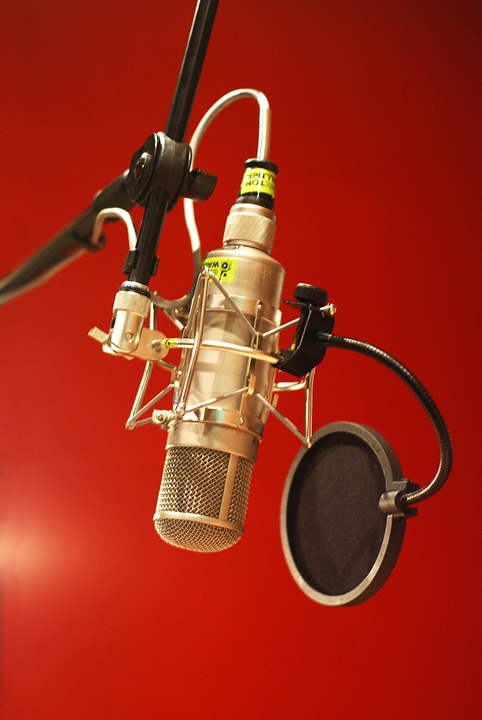
Above: A studio microphone for a vocalist. The microphone is
in a separate
mechanical shock mount with an external wind screen.
Photo: Pixabay
Stand mounted
These are the attributes of a stand-mounted microphone:
- Reach for studio quality outside of a studio environment
- One-piece attachment to the stand
- Standard XLR connections
- Somewhat rugged
- A stand helps the sound engineer take advantage of the directional characteristics of the microphone.
Some microphones are designed to be mounted on a stand. They usually include good mechanical shock-mounting and a wind screen in one unit to reach for studio-quality with less fuss and set-up time. A common design to achieve this is the birdcage style. Here the capsule, shock-mount, and windscreen are protected inside a cage. The Shure model 55S is a common example, but many manufacturers make microphones in this style. These microphones are simply too big to be conveniently hand-held, so they must be used on a stand. The stand also allows the sound engineer to position and aim the microphone carefully, which is an advantage, unless the vocalist starts tipping the stand around, Elvis-style!
A good-quality microphone that is designed to be hand-held but instead is clipped to a stand can be every bit as useful as a microphone designed to be mounted on a stand. The main advantage of mounting a microphone on a stand is that it can be pointed away from loudspeakers and toward the sound source in a dependable way. A microphone that is held by a person is likely to be pointed all around the room at various times.
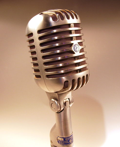
Above: A typical "birdcage" style microphone.
(Shure model 55S) Photo:
Wikimedia Commons

Above: Sometimes the microphone stand is a stage prop too!
(Elvis Presley, 1956.) Photo: Wikimedia Commons
Installed microphone
These are the characteristics of installed microphones:
- Theft resistant or otherwise specially located and fastened in place.
- Often designed for public address systems (usually speech, occasionally music).
- Rugged—frequent use by various personnel—or low visibility, e.g. choir mic.
- Fastened to a table, suspended from a ceiling, fastened to a police radio, etc.
- Also could be built into a computer, camcorder, cell phone, intercom, etc.
- Also could be built into a helmet, or on a headphone with or without a boom.
- Occasionally used in house-of-worship applications for choir or room mics.
- Was common in house-of-worship applications for the pulpit mic.
Installed microphones are designed to be always present and ready, requiring no set-up time and no training to use. They are impossible to misplace or disconnect because they are bolted down and more-or-less permanently wired in place. They must be rugged enough to withstand use by ordinary people, in contrast to microphones used by professional performers. Installed microphones need good mechanical shock mounting to prevent noises from the podium or counter-top or other structure to which the microphone is fastened from being conducted into the microphone.
Installed microphones used to be preferred (1930's through 1970's) in house-of-worship applications in order to minimize set-up and take-down time. In some of these situations the public address system was simply turned on or turned off. There was no sound operator on duty during worship. Most houses of worship have now abandoned that concept and many installed microphones have been removed and replaced with other options. Those installed microphones that remain might be used only as backup options or otherwise abandoned.
Installed microphones are usually designed for spoken-word applications as opposed to music. This usually implies prominent sensitivity to upper-midrange frequencies where the human voice has a lot of energy. This makes spoken words easier to understand as compared to uniform frequency response, even if it is not particularly high-fidelity. Sometimes, especially in house-of-worship applications, a soloist or small ensemble of vocalists will perform from a podium with an installed microphone. If the microphone is not one designed for music, the results can be a bit on the shrill side.
The category of installed microphones also includes microphones that are suspended from a ceiling to pick up sound in a conference room, or from a choir, or congregational singing, etc. These microphones do not need shock mounting, but usually their size should be minimal to avoid obstructing sight lines in the room. Very often these microphones have a captive cable, meaning a long cable (say 15 or 20 feet) that is permanently attached to the microphone. The cable that conducts the electrical signal is also designed to have the mechanical strength to suspend the microphone while being as thin as possible for aesthetic reasons.
The category of installed microphones also includes microphones built into other appliances, such as a laptop computer, cell phone, intercom system, etc. Once again, quality shock mounting matters. For instance, on a laptop computer the microphone should not be able to pick up the sound of the keyboard being used. (But that's a pretty tall order.) Or the microphone might be built into a helmet or headphone.
Sometimes a microphone that is designed as a hand-held microphone is clipped to a gooseneck that is permanently fastened to a podium or table top. Functionally, this usually works fine, assuming the microphone has a good internal shock-mount. It can even have superior performance since some hand-held microphones are higher fidelity than some microphones that are designed to be installed. Practically however, the microphone can be easily removed from the clip and disconnected from the cable. Even if potential theft is not an issue, the microphone might be absent without leave when it is needed because someone temporarily borrowed it for another purpose. Also, in this type of installation the microphone cable is usually visible and subject to additional wear and potential abuse, as opposed to a cable that is internal to the gooseneck.

Above: An installed microphone. The sound of moving drinking
glasses etc.
on the tabletop can be conducted up the gooseneck, thus
good shock mounting
of the capsule in the microphone is needed.
Photo: Wikimedia Commons
Handheld
These are the characteristics of a handheld microphone:
- reduces the ability of the speaker to gesture or manipulate papers.
- Windscreen is essential. Additional windsock over the screen is often helpful.
- Internal shock mount is essential.
- Ruggedness, drop resistance, is important.
- Size, shape, color, etc. are a matter of fashion.
- Can be styled for fashion by adding a colorful windsock, painting the handle, etc.
- Should be held by the handle. Fingers must not touch wind screen.
- Most are directional, but if handheld it might be aimed in random directions.
- Can be fastened to a stand using a microphone clip, then aimed carefully.
Handheld microphones need to be conveniently held; hence the typical size is about that of an ice-cream cone. Some of them are designed in a stylish way for use on camera in television work. The size of these stylish microphones has little to do with basic physics and electronics and more to do with fashion. A few are more stem-like to appear more stylish on camera in some situations. There is a small market in customizing handheld microphones so that they coordinate with clothing, sets, etc. An inexpensive customization is to fit it with a colorful windsock.
Most voices sound better, with less popping and hissing, if an additional
windsock is fitted over top of the standard screen on the microphone.
However, professional vocalists who are aware of the need to avoid excessive
plosives can sound better without additional windscreening.
The person holding the microphone should be instructed to hold it by the
handle and not allow any fingers to touch the wind screen. Fingers and
hands near the capsule block sound. It is counter-intuitive to most people,
but cupping the microphone blocks sound from traveling clear through the
windscreen system, thus creating distortion in the sound. You don't speak through
your nose but pinching off your nose while talking creates an unpleasant
sound! Similarly, blocking the back of a microphone creates a bad sound.
Video: How to hold a microphone.
That said, some singers still like to cup the microphone. It can be done
in a way that accentuates mid-pitched sounds, making the vocalist seem
closer to the listener, but usually at great compromise to overall fidelity.
In this video the
speaker is incorrectly holding the microphone from
0:30 to 2:10. At 2:10 he moves his hand and corrects his hold on the
microphone. The improvement in the audio is easily heard if you are
listening with a good sound system or good headphones. (A tiny smart-phone
speaker might not show difference.) This example is just speech. The
difference with vocal music can be even more obvious, but this is the
example I was able to find. (Just watch from about 1:00 to about 3:00.
The author of How Sound—these pages—does not particularly endorse lock-picking!
Do you know of a better example video? Please e-mail me!)
Hand-held microphones fully occupy one hand of the vocalist which reduces the ability of the vocalist to gesture or manipulate papers. A vocalist might reflexively gesture or manipulate notes with the hand that is holding the microphone, resulting in inconsistent sound. Although most hand-held microphones are directional, the sound operator cannot depend on this directionality being used to advantage. Unless the person using the microphone understands how to use it well, the aim of the microphone can be best controlled by fastening the microphone to a stand using a microphone clip. This frees the vocalist's hands and gives the sound engineer an opportunity to aim the microphone carefully to minimize the pickup of feedback and other undesired sources and maximize the pickup of the desired source.
A handheld microphone is likely to be dropped onto hard floors now and then. It must be able to survive. Handheld microphones also need to have the capsule mechanically-shock-mounted so that handling noise (picking up and setting down the microphone, handing the microphone from one person to another, sound from stroking the microphone wire) is minimized. A handheld microphone usually needs a substantial wind screen to mitigate the sound of the wind going past the microphone as it is waved through the air. (For example, when a singer lifts the microphone from near waist height to their mouth to begin singing, the breeze going past the capsule would be substantial save for the windscreen.) Windscreens having larger and softer and shaggier surfaces are more effective.
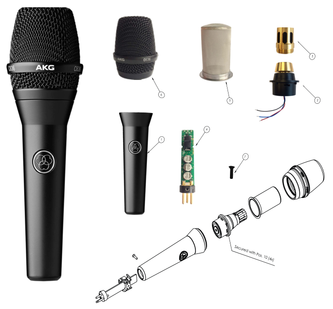
Above: The parts of a typical hand-held microphone. 1. Handle, 2. Shock-mount,
3. Capsule, 4. preamplifier, 5. Internal windscreen 6. External windscreen.
Click on the photo for a higher resolution view.
Photo ©2018 by AKG.com Used by permission.

Figure 7. Stem-style hand-held microphone. (American model D22)
Oh yeh, the other subject in this photo is Bing Crosby.
Photo: Ampex advertisement from the 1950's, fair use
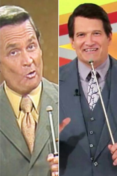
Figure 8. Hand-held microphone with telescoping stem. (Sony ECM-51)
Photo: Brandon Lee Bryant Low resolution--fair use.

Figure 9. This sounds terrible. Hold it by the handle instead.
Sometimes people want to sound terrible, but otherwise,
give them some basic instructions.
Photo: Pixabay
Video: Proximity effect and directionality
Boundary or Pressure-Zone or PZM microphones
These are the characteristics of a boundary microphone:
- Miniaturized enough to place the diaphragm very close to a boundary.
- A flat and thin microphone, typically about 4" x 4" x 0.5"
- Windscreen, if present, is probably minimally effective due to small size.
- Shock mount is impractical due to miniature size.
- Designed to avoid comb filtering effects from reflected sound.
- Sometimes used inside pianos.
- Not a very popular microphone due to its specialized design.
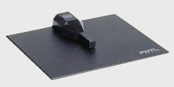
Figure 10. A typical boundary zone microphone.
Photo: Wikimedia Commons(modified)
The short and skinny story about boundary zone microphones, which are also known as
pressure zone microphones and PZM microphones is that they are rarely used in house-of-worship
applications except possibly inside pianos, especially grand pianos.
When an extreme amount of
amplification is desired one or more boundary zone microphones can be
adhesively fastened to the underside of the lid of the piano and the lid can be closed to
achieve a strong and highly isolated signal. Since the piano lid is fully closed the stage
area around the piano is relatively quiet compared to having the lid open on full stick with
the microphone(s) outside the piano. But even this use of boundary zone microphones is not
very popular in house-of-worship applications because higher fidelity techniques are possible.
The interested reader can find out more about boundary zone microphones from the
Wikipedia article on this topic.
Lavalier or Lapel-mounted
These are the characteristics of a lavalier microphone:
- Miniaturization subject only to durability.
- Windscreen, if present, is probably minimally effective due to small size.
- Usually clipped to clothing, but there are other choices possible.
- Lavalier microphones are very popular for video recording. Most instructions assume the application is video.
- For live sound, overall tone can be inconsistent as the person wearing the mic moves.
- Shock mount is impractical due to miniature size.
- Most are omnidirectional, but other options are available.
- Have strong high-frequency boost to make speech sound normal overall.
- Not particularly high-fidelity. Usually not suitable for singing.
- Not suitable for attaching to musical instruments (guitar, violin, etc.)
- Sound shrill, with pops and rustling sounds if hand-held.
- Keeps the speaker's hands free for holding a book or gesturing.
In thinking about where this type of microphone would be in the 3-D space of miniaturization-directionality-fidelity, the miniaturization is becoming extreme enough to cause noticeable compromises. This is located quite far from the origin of the 3-D space but also quite near the miniaturization axis.
Lavalier microphones usually compromise the shock mounting and are made omnidirectional to make the microphone smaller. Directional lavalier microphones are available; however, they are larger and harder to hide in clothing or hair. If there is a windscreen, it is likely to be only slightly effective due to its small size. Lavalier microphones are usually clipped to clothing.
For live-sound applications (Most house-of-worship applications) the microphone works best when mounted near the place on the chest where the person's chin touches if the head is lowered until the chin touches the chest. This is about three inches higher than the best place for recorded sound work. The place where the chin can touch gives a stronger signal that is less prone to feedback and needless echo. In recorded work there is no amplified sound to overcome, so a slightly lower position can be used to achieve a somewhat more natural tone and to keep the microphone out of the video frame on closeup shots. Its small size then helps disguise it on long shots. Mounting the microphone too low also increases the risk of picking up stomach rumble sounds! No matter how the microphone is mounted, if the speaker turns his or her head far to either side, the sound level tends to drop. (If you are reading other literature on the topic of placing a lavalier microphone, pay attention to the application. Is it live-sound, recorded sound with no video, or video with audio? Each requires a different optimization.)
Lavalier microphones are designed to be mounted to a soft sound-absorbing surface such as clothing, or even skin (use medical first-aid tape). The sound this close to such a surface will naturally be a little muffled. To combat this, all lavalier microphones are designed to boost the higher frequencies so that the sound they send is normal sounding. The high-frequency boost is usually created by the acoustic properties of the capsule's materials, as opposed to using an electronic filtering circuit. An acoustic boost of high frequencies does not also boost electronic noise like an electronic filter does. Thus, using a hand-held microphone on a necklace and using an equalizer to achieve the needed high-frequency boost, does not perform as well as using a lavalier microphone in the first place.
A lavalier microphone with it's built-in acoustic high-frequency boost is well and good as long as the microphone is used as intended. Occasionally a speaker will, in an impromptu moment, remove his or her lavalier microphone and hand-hold it (or finger hold it?) to pick up a guest speaker standing nearby. This always results in a tinny sound due to the built-in high-frequency emphasis. Also, the microphone typically has no shock mounting and no wind screen (or only a slightly effective wind screen). Thus, the results of hand-holding a lavalier microphone are inevitably poor, with lots of rustling noises, popping sounds, and shrillness. If the need to offer a microphone to a guest can be anticipated, it would be best to offer the guest almost any other type of microphone (say a wireless handheld microphone) rather than hand-holding a lavalier microphone. Also, due to the built in high-frequency sensitivity, a lavalier microphone is a poor choice for a musical instrument (guitar, violin, etc.).
In a house-of-worship application the main advantage of a lavalier microphone is the freedom of hands and movement that the microphone affords. Almost any other microphone type will give better quality sound for the money. That goes double for a lavalier used on a person who is singing, since audio fidelity matters more then.

Above: A well-placed (for live-sound) lapel microphone on George Forman.
Photo: Wikimedia Commons
Head-worn
These are the characteristics of a head-worn microphone (also known as a head-set
or ear-set microphone).
- Miniaturization at all costs—even to the point of fragility.
- Windscreen, if present, is probably minimally effective.
- Provides very uniform sound pickup regardless of the person's activity.
- A good choice to suppress feedback, if feedback is a problem.
- Keeps the speaker's hands free for holding a book or gesturing.
- Small enough to be virtually invisible if worn correctly.
- Can be hidden in hair or a beard if so desired.
- capsule usually is placed about 1/2 inch back from the corner of the mouth, but there are other possible choices.
- Most people wearing a head-worn microphone are at least slightly annoyed by it.
- Shock mount is impossible due to miniature size, but there is little mass to cause trouble.
- Most are omnidirectional, but other options are available.
- Some have limited ability to handle shouting, loud singing, due to miniaturization,
- Extreme pops and rustling sounds if used as a hand-held (finger-held?) mic.

Above: Garth Brooks wears a Crown CM331A head-worn microphone.
Wikimedia Commons
One of the primary advantages of a head-worn microphone is that it moves
with the speaker's head and maintains a very constant distance to the source
of the sound. Another advantage is that although the microphone is in plain sight,
the smallest of them are small enough to disappear from view at a distance or on video
if they are worn properly. To this end, most of the small models are available in
a variety of colors to match different skin tones. Also, to the end of allowing
the microphone to disappear from view, the microphone can be worn in such a style
as to allow natural shadow lines along the jaw to camouflage the microphone. To make such
camouflage effective the microphone must lay on or very close to the skin
(within 1/4 inch or less). Otherwise, shadows and highlights from ordinary
lighting give the microphone away, even accentuating its visibility.
Sometimes a head-worn microphone is used mainly to fight feedback. If this is
the case, the best place to locate the microphone capsule is about 1/2 inch
back from a smile and in line with the speaker's lips.
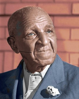

Above: George Washington Carver and George Washington are
each wearing a head-worn microphone in the ideal location for
picking up the maximum signal practical, thus giving the
maximum gain possible before feedback sets in.
Wikimedia Commons
and Wikimedia Commons
(both marked up)
Usually maximization of gain-before-feedback is not needed. Furthermore, head-worn
microphones are typically extremely sensitive to plosives. If the microphone
is any closer to the lips than is shown above then distortion of plosives
becomes a possibility.
Usually, it is best to position the microphone to achieve camouflage rather than to
minimize feedback. There is a natural shadow-line on the front of the jaw. If the
microphone is located as if to extend this shadow-line all the way back to
underneath the earlobe, the eye of the viewer will overlook the microphone.
If a shirt is worn with an open collar, be sure the microphone is not
so low on the jaw as to possibly rub on the collar. Even at this location,
the microphone is just a few inches from the speaker's mouth and a good
strong signal is available.
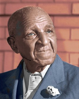

Above: George Washington Carver and George Washington are
each wearing a head-worn microphone in the ideal location to
camouflage it, giving the microphone the least visibility.
Wikimedia Commons
and Wikimedia Commons
(both marked up)
Sometimes the speaker has difficulty getting the microphone to fit well. In this case the mic may hang in mid-air an inch or more from the speaker's face. Distance between the mic and the face causes the microphone to become distractingly visible against the background. Ideally the sound technician should work with the speaker to get the microphone placed well so that the speaker is comfortable with the microphone and does not have to fiddle with it during the worship service and so that the microphone is mounted optimally for the needs of the situation.
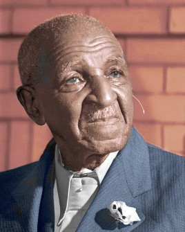

Above: George Washington Carver and George Washington have
been given no help from the sound tech. Although this location
for the microphone seems intuitive, it optimizes nothing.
Wikimedia Commons
and Wikimedia Commons
(both marked up)
If you have a choice of colors for the microphone, choosing a color that is
slightly darker than the speaker's face will disguise the microphone better
than choosing a color that is slightly too light. This works best because
the lighting on the podium will typically cause a few spots of glare or
specular reflection from the microphone. A slightly darker color will offset
the glare and give a better overall color match.
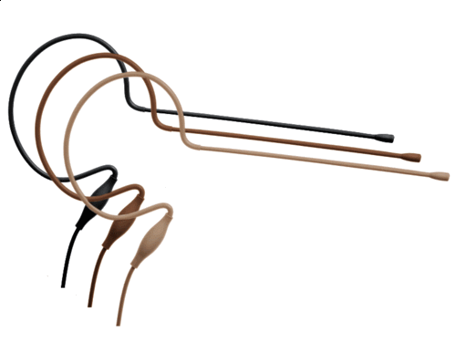
Above: Head-worn microphones are often available in a variety of colors.
Product photo, MM-PSM Pro Series, fair use.
Head-worn microphones tend to be fragile. To make them small and
nearly invisible the boom of the microphone and all the other parts are made of
the thinnest possible materials. Whereas a handheld microphone might have a
useful life of twenty years or more, most head-worn microphones seem to have a
useful life of less than three years. They are nearly a "consumable" quantity.
When budgeting for a head-worn microphone, plan on purchasing and keeping on hand
a spare microphone. The day will inevitably come when you need to make a fast
replacement.
Three factors that are unique to head-worn microphones contribute to their fragility.
1.) They get bent. To provide a comfortable and effective fit it is
necessary to bend the boom and ear-loops of the microphone. Eventually the metals
fatigue and crack and then the microphone will need to be replaced. 2.) The wire
gets flexed a lot. The wire that leads from the microphone also gets bent with every
turn of the speaker's head. Considering also that the wire has been made as thin as
possible, this wire has a limited lifespan. Some head-worn microphones can be ordered
with different options for the wire: a thin option for invisibility and a thicker
option for durability. 3.) The capsule of a head-worn microphone is unusually
vulnerable to any dirt that might enter the front of the microphone. Especially if the
microphone is used in an environment where food may be present there is the possibility
that the microphone will be handled by fingers that have food residue on them. This
residue can be accidentally introduced into the front of the mic. Once dirt enters,
it muffles the signal. This type of dirt is difficult to clean out. Some microphones
have specific instructions for cleaning, usually involving rinsing with distilled or
deionized water and drying under specific conditions. But these procedures do not
always work. Some dirt is insoluble.
The wire that leads from the head-worn microphone to the bodypack tends to pull the
microphone out of position. To prevent this, a clip should be used to fasten the
wire to some clothing. There should be a enough of a loop of wire between the
head-worn mic and the clip to accommodate the full range of turning of the head
from side-to-side. Typically, the clip can be fastened to a collar on the back of a
shirt or blouse. Then the clip should be about nine or ten inches down the wire
from the back of the microphone. As you follow the wire from the microphone to
the clip, the wire should enter the clip on the opposite side from where the
microphone is, as illustrated below. This causes the loop of wire to fall on
the person's back. If the wire is lead the other way through the clip, then the loop
has an unsightly tendency to fall over the person's shoulder instead.
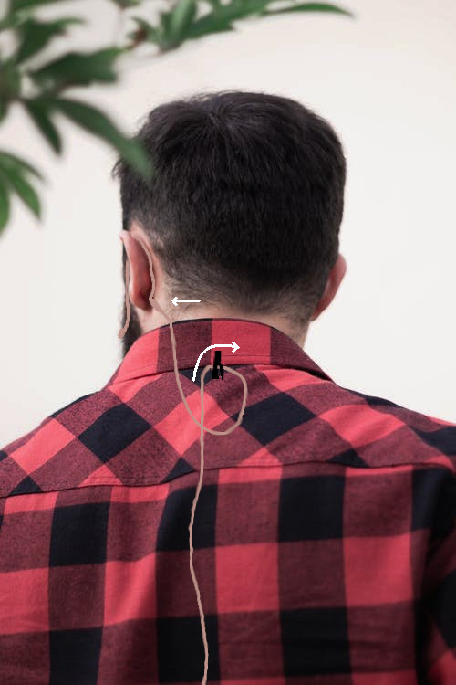
Above: The wire leading to the microphone should be clipped to clothing.
As the wire exits the clip on its way to the mic it should face away from the
microphone so that the loop of wire falls on the center of the person's back.
Pexels stock photo marked up
Jewelry, especially earrings, can occasionally rattle against a head-worn mic
causing considerable noise and distraction in the signal. In certain cases it
may be better to resort to a lavalier or stand-mounted microphone.
This ends the discussion of miniaturization of microphones. In order from
largest to smallest, studio, stand-mounted, installed, handheld, boundary, lavalier,
and head-worn microphones have been discussed. The smaller the microphone is,
the harder it is to make it directional and high-fidelity.
2.) Directionality (vs. miniaturization and fidelity)
It is relatively easy to make a microphone that is not at all sensitive to the
direction of the sound as the sound approaches the microphone. As the sensitivity
of the microphone to the direction of the approach of the sound waves is increased
the microphone becomes increasingly difficult to miniaturize and it becomes more
difficult to maintain high-fidelity audio reproduction.
A microphone that to some extend is insensitive to sounds from the sides and/or
the back of the microphone is said to to be directional. In a narrow technical
and mathematical sense, it is helpful to think of the amount of directionality
as the relative sensitivity to sounds arriving on-axis compared to the sensitivity
(or better, the in-sensitivity!) of sounds arriving perpendicular to the axis.
A perfectly directional microphone rejects sounds arriving at a 90°
angle to its axis. Notice that nothing has been said in this definition about
rejection from the rear of the microphone. That's a bit counterintuitive, but
that is the mathematical way to think of it. Of course, in practice, whatever
directional pattern works is what we will use, even if in the technical-mathematical
sense it might not be the most directional microphone that could be chosen.
Microphones with near perfect rejection from the back are common, but these
are somewhat sensitive to sounds from 90° off axis. Even though these
are not the mathematically most directional microphones, we like them!
A microphone that is completely insensitive to directionality is said to be
omnidirectional. The next step in increasing the directionality of the
microphone results more in a microphone that rejects sounds from the back.
This type of microphone accepts sounds from lots of directions, except
directly from the back side, from which it is designed to reject sound.
This type is called cardioid. The next step of increased directionality
has a goal of narrowing the angle of acceptance of sound as a higher priority than
rejecting sound from the back of the microphone. This is a super-cardioid,
also known as an hyper-cardioid microphone. Continuing to make the
microphone more directional eventually results in a microphone that completely
rejects sounds from the sides (from 90° off axis) but accepts sounds equally
well from the front or back. This is a bi-directional microphone,
also known as a figure-of-eight microphone. Finally, microphones that are
designed to be more sensitive to on-axis sounds than sounds from the sides and
the rear are the shotgun or parabolic microphones.
Shotgun and parabolic microphones tend to be the largest
and lowest-fidelity microphones. Every compromise possible has been made to
enhance directionality. In contrast, at the other end of the
directionality spectrum, omnidirectional microphones
will be the easiest to miniaturize and will tend to deliver the highest fidelity
because nothing needs to be compromised to promote directionality.
Before explaining each of the different types of directional microphones it is
helpful to understand how the direction of a sound wave is evident to a microphone.
Sound waves are longitudinal waves. They are created by the motion of air molecules.
In the illustrations below, each black dot represents an air molecule. Sound causes
these molecules to vibrate in a pattern that creates compression zones (a higher
density of molecules) and rarefaction zones (lower density of air molecules) that
form in lines. These lines move in a continuous direction—the direction in
which the sound is traveling. In the caption below the first illustration there is a link
to a web page that includes an animation of the illustration below. The animation
is valuable for visualizing how sound moves through air in a particular direction.
The first illustration below is valid for a source of sound far away, say three feet or
more away. The illustration that includes a vocalist shows how the lines of compression and rarefaction
in a sound wave are curved and spherical at their source and that they get weaker as they expand outward.
Whereas the groupings of compression and rarefaction move
outward from the source, the air molecules just bounce back-and-forth for an ordinary
sound wave. This can be most clearly seen in the first animated illustration linked below.
Not illustrated here is a plosive soundwave, in which there is a
sudden addition of air molecules at the source creating a puff of wind in addition
to the longitudinal waves. Pronunciation of letters p, b, t and some others create
some plosive sound as well as longitudinal sound.
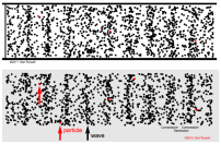
Above: A visualization of sound in air. Please check out the
animation of the above illustration.

Above: A visualization of sound in air close to the source.
Longitudinal waves have a spherical shape close to the source and their
intensity
fades as they radiate outward.
Pixabay (edited).
These characteristics of how sound travels through air are important in understanding
how microphones are made directional and how to make best use of directional
microphones.
 Omnidirectional
- All directional, rather "musical" to most ears.
- Resistant to wind noise and plosives in speech
- Simple construction leads to high-accuracy sound pick-up
- Keep omnidirectional mics close to sound sources in live-sound applications, else feedback.
At any single point in the sound field there is only a pressure difference between the compressed areas and the rarefied areas. As these areas pass over a single point a signal representing the pressure changes can be derived. The direction in which the sound is traveling does not matter

Above: The arrow shows the direction of sound waves.
The blue box represents an omnidirectional microphone. The small portion
at the top senses the pressure at that point.
Illustration by Prof. dDB.
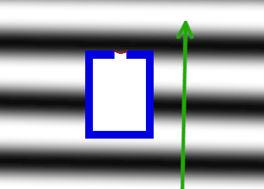
Above: The direction of the sound does not matter. Even if the
direction was completely reversed, or turned to any angle, the pressure
changes at the sensitive point of the microphone are equally easily sensed.
Illustration by Prof. dDB.
Omnidirectional microphones are somewhat insensitive to wind noise (e.g. outdoors)
and plosives from "p," "b," "s," and "t" sounds. This is because wind (air velocity)
does not correspond directly to waves of pressure or rarefaction. This is an
important advantage of omnidirectional microphones. Wind rushing over the housing
of the microphone can produce turbulence that can create some pressure-waves thus
inducing some wind noise, so wind screening is still appropriate in many situations,
but in general, omnidirectional microphones resist wind noise better than directional
microphones.
The directional pattern of a microphone can be expressed as a polar plot of gain
relative to on-axis gain. In the plot below, the "0" degree mark (where 3 o'clock
would be on an analog clock face) represents the ability of the microphone to
pick up sounds on-axis. (The ability to pick up sounds with the microphone pointed
directly at the sound.) On all polar patterns, this has a unit of "1" or 100%,
meaning that for sounds approaching the microphone from this angle (zero degrees)
relative to the axis, 100% or 1.0 units of the sound will be picked up. For an
omnidirectional microphone the plot is uninteresting because, as the heavy (blue)
line indicates, the microphone picks up 100% of the sound when it arrives at any
angle. The plot is shown here mainly for comparison to the plots for directional
microphones.
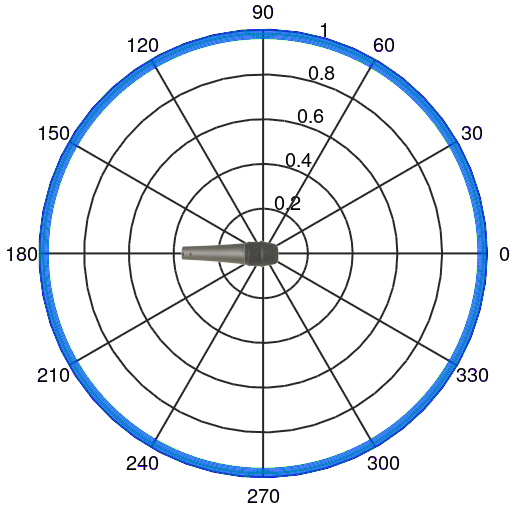
Above: The ideal omnidirectional pattern. The numbers around the outside of the
plot show the angle, in degrees, from which a sound may arrive. The numbers between
0 and 1 on the radius to the right of 90 degrees label the fractional amount of sound
that might be picked up relative to an on-axis arrival. If you multiply this number
by 100 you get the percentage of sound that might be picked up relative to an on-axis
arrival. The heavy (blue) circle around the outside indicates that an omnidirectional
microphone picks up sound equally well from any angle.
Illustration by Prof. dDB.
Most omnidirectional microphones have a directional pattern very close to the ideal pattern shown above for frequencies below 5 kHz. Considering that the highest note on a piano is about 4 kHz, this covers all the fundamental frequencies and even some harmonics of voices and most musical instruments. However not everything is so perfect. Most omnidirectional microphones, especially those in larger housings, show some slight lack of sensitivity from the rear as frequencies go above 5 kHz. This will matter mostly for miking high-frequency instruments such as a piccolo or cymbals, tambourines, etc. The plot below shows a pattern that is more typical of an actual omnidirectional microphone at about 8 kHz.
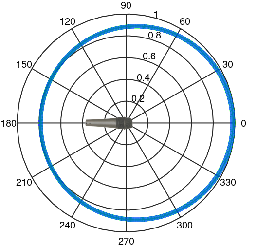
Above: An achievable practical omnidirectional pattern for high frequencies.
This plot could be typical of 8 kHz sounds. The numbers around the outside of
the plot show the angle, in degrees, from which a sound may arrive. The numbers
between 0 and 1 on the radius to the right of 90 degrees label the fractional
amount of sound picked up relative to an on-axis arrival. The heavy
(blue) nearly circular line indicates that a practical omnidirectional
microphone picks up a little less high-frequency sound from the rear.
Illustration by Prof. dDB.
The slight directional effect of omnidirectional microphones is usually so minimal
as to be negligible for all except a few applications, and even then, omnidirectional
microphones handle off-axis sounds with less distortion than any directional microphone.
For acoustic instruments on a quiet stage (no other nearby competing instruments or
voices) omnidirectional microphones typically produce especially pleasing results
relative to equally expensive directional microphones. But a quiet stage is a seriously
restrictive qualifier in most live-sound environments, unless perhaps there is a solo
instrument. Omnidirectional microphones are more common in a studio environment for
recorded sound. Omnidirectional microphones in live-sound house-of-worship
applications are mostly limited to lavalier and ear-set microphones where
their ability to be miniaturized matters.
Omnidirectional microphones are also inherently superior to directional microphones of
equivalent cost when uniformly accurate and smooth high-fidelity low-frequency response
is needed. Pianos (the low notes extend down to 27 Hz), Pipe organs (some go down to 16 Hz),
bass violins, contrabassoons, and electric bass cabinets can sometimes benefit from using
an omnidirectional microphone because of the inherent low-frequency advantage of this
design. Not all omnidirectional microphones achieve such excellent low-frequency
response, so be sure to check the datasheet before purchasing. However due to feedback
concerns in live-sound, omnidirectional microphones are not a common choice, even when
good low-frequency response is helpful.
If omnidirectional microphones are used in live-sound reinforcement their ability to
pick up sound from all angles means they are more open to picking up feedback. This is
a serious strike against the routine use of omnidirectional microphones in live-sound
reinforcement. This disadvantage may be overcome by keeping the microphone very close
to the sound source, which is exactly what ear-set and lavalier microphones do. (Also,
whenever possible keep the mic behind the loudspeaker so that the directional pattern
of the loudspeaker directs amplified sound away from the microphone.)
Within the category of omnidirectional microphones there is a category of microphones
called "measurement" microphones or "reference" microphones. These use standard XLR
connections and look like any microphone, and superficially they act like any
microphone. But they are optimized for use with spectrum analyzers for scientific
laboratory work, not audio mixing boards. It is not impossible to use this type of
microphone in a house-of-worship application, but it is unlikely to be your best choice
for the money in this application. Many of them have restricted dynamic range. They
overload easily and they might have higher background noise than a normal microphone.
What they do have is ultra-flat frequency response. It is usually best not to order
one of these for live-sound house-of-worship reinforcement.
 Figure-of-eight
- Bi-directional. Rejects sounds from the sides.
- Especially sensitive to wind noise and plosives in speech
- Strong proximity effect.

Above: The arrow shows the direction of sound waves.
The blue area represents the capsule of a figure-of-eight microphone.
As the air-molecules move against the diaphragm (thin red line) the
diaphragm follows their motion, creating a signal.
Illustration by Prof. dDB.
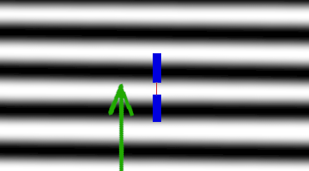
Above: The direction of the sound matters. If the sound arrives
perpendicular to the axis of the capsule, as shown, then it creates no
motion of the diaphragm, and there is no signal.
Illustration by Prof. dDB.
Directional microphones, and especially Figure-of-eight microphones
are sensitive to wind and especially the turbulence of any breeze that
might flow past the capsule. This makes them especially sensitive to
plosives such as "b," "p,", "s," and "t" in speech. These microphones
will emphasize these sounds if the microphone is close enough to the
source. The effect starts to become noticeable within a foot or so
of the person speaking and can become obnoxious if the microphone is
very close and has no windscreen. For speech and vocal reinforcement
wind screening becomes essential with these microphones.
The directional pattern of a figure-of-eight microphone is shown below.
Notice that the sound is equally well received from the rear as well
as from the front, but at an angle perpendicular to the axis the microphone
is totally insensitive. Thinking of directionality as being the ability
of the microphone to reject sound from the side—from 90 degrees
off-axis—the figure-of-eight pattern is the most directional pattern
possible. In theory at least, it achieves perfect directionality in this
conception of directionality.
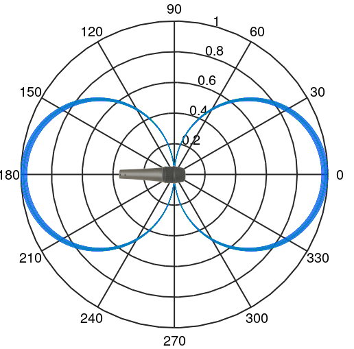
Above: The ideal figure-of-eight pattern. The numbers around the outside of the
plot show the angle, in degrees, from which a sound may arrive. The numbers between
0 and 1 on the radius to the right of 90 degrees label the fractional amount of sound
that might be picked up relative to an on-axis arrival. If you multiply this number
by 100 you get the percentage of sound that might be picked up relative to an on-axis
arrival. Maximum rejection of sound is at angles perpendicular to the axis of
the microphone.
Illustration by Prof. dDB.
Figure-of-eight microphones are essentially sensitive to the velocity of the moving
air molecules in a longitudinal sound wave. In contrast, an omnidirectional
microphone is essentially sensitive to the pressure variations (density of air
molecules) in a sound wave. Recall the animation
which shows the two different aspects of a longitudinal sound wave. In this
animation a figure-of-eight microphone is sensitive to the motion of the "particle"
and an omnidirectional microphone is sensitive to the "wave." Thus, an
omnidirectional microphone is said to be responsive to pressure and a
figure-of-eight microphone is sensitive to velocity. (Velocity sensitivity
is also known as pressure gradient sensitivity. Mathematically, a gradient
is a directional derivative. Velocity is the gradient of position. For sound in
air, a pressure gradient is proportional to the velocity of air molecules.)
Figure-of-eight microphones, when placed very close to a source of sound (usually
within one foot or closer) give exaggerated bass (low frequency) response. This is called
the proximity effect. It is caused by the curvature of the sound waves
near the source. As the waves radiate outward from the source the circumference of each
wave-front increases resulting in weaker pressure gradients (weaker sound) being
associated with the further wavefronts. Moving a microphone from one inch away
from a source to four inches away, a motion of three inches, makes a big difference
in the strength of the sound at the microphone. However if the microphone is moved
from thirty-one inches to thirty-four inches away—an identical three inch
movement— there is hardly any difference in the strength of the sound at the
microphone because the waves at those greater distances are hardly curved at all.
If a figure-of-eight microphone is very close to the source of sound, the sound
at the side opposite of the sound source, say the rear side of the microphone, is
just a little bit weaker than the sound at the front because the back side of the
microphone is just a little further from the source then the front side of the microphone.
(Or the sound has to travel just a little further to get to the back side of the
diaphragm of the capsule.) Some of this difference depends on the size and geometry
of the microphone capsule, the diaphragm, and the structural elements (which may block
some sound waves) required to support the diaphragm. This means that some microphones
have larger proximity effects for a given distance to the sound-source than others.
In a counterintuitive way, weaker sound at the back of the diaphragm reduces the
overall sensitivity of the diaphragm. However, as the frequency of the sound
gets lower its wavelength gets longer which means that the distance the waves have
to travel is less important. Thus, lower frequency sounds get picked up better
than higher-frequency sounds when the sound waves are curved.
Proximity effect is inherent in any velocity-sensitive microphone.
Fundamentally, some proximity effect will always be inherent to achieving directionality.
Although in a technical sense the proximity effect is distortion, most people find
that a small or moderate amount of it sounds pleasing, adding a sensation of closeness
or authority. This is true for both male and female voices. The lack of proximity
effect in omnidirectional microphones is one reason why they are not so frequently used
for speech and vocals. However for musical instruments the proximity effect can sometimes
be obnoxious, causing certain low notes to ring out obtrusively. If directional microphones
are used for musical instruments that have low notes, e.g. piano, cello, bass violine, etc.
it is important to keep the microphone at least several inches from the sound-producing
parts of the instrument, such as the sound-board or the strings. (Unless you are
deliberately trying for a honky kind of sound, say for a special effect.)
Of all the directional microphone designs, figure-of-eight microphones display the
strongest proximity effects. Only omnidirectional microphones are completely free
of the proximity effect because they sample the sound at a single point. Click here
for a demonstration of proximity effect.
(Headphones or earbuds with good low-frequency
response will help you hear the demonstration accurately.) One may also note that
directional microphones eliminate most room resonances from the sound, mainly because
room resonances arrive from all directions, making an omnidirectional microphone
especially sensitive to them.
An equation can be used to describe the directionality of a microphone. In the
equation below, θ is the angle of arrival of the sound. If θ = 0 then
the sound is arriving on axis, directly into the front of the microphone.
If θ = 90° then the sound is arriving at a perpendicular angle directly
into the side of the microphone. And if θ = 180° then the sound is
arriving directly from the rear of the microphone. Also in this equation the
variable d represents the directionality of the microphone. The variable
d can range from zero to unity. If d = 0 then the microphone is
not directional, it is omnidirectional. If d = 1 then the microphone is
fully directional, it is a figure-of-eight microphone. Finally, S(θ)
represents the amount of sensitivity of the microphone at angle θ. The
sensitivity, S(θ) will always be 1 (or 100%) for θ = 0.
At other angles it can vary from 1 down to 0, zero being completely insensitive.
S(θ) = |(1 – d) + dcos(θ)|
The above equation is the equation that was used to generate the figures illustrating
the directionality of omnidirectional (d = 0) and figure-of-eight
(d = 1) microphones. But the directionality amount, d does not
have to be exactly zero (0) or exactly unity (1). It can be any amount in
between those limits. This equation nicely illustrates that omnidirectional
microphones and figure-of-eight microphones represent two extremes of a continuum.
Other patterns such as cardioid, and super-cardioid, are achieved with different
directionality factors, d.
 Cardioid
- Easily understood pickup pattern—picks up from front, rejects from back.
- Can help reduce feedback problems
- Pleasant and mild proximity effect
- Sounds entering from the rear or sides can be distorted.
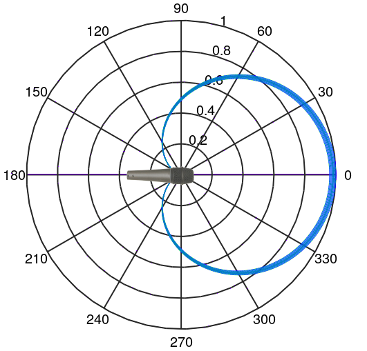
Above: The ideal cardioid pattern. The numbers around the outside of the
plot show the angle, in degrees, from which a sound may arrive. The numbers between
0 and 1 on the radius to the right of 90 degrees label the fractional amount of sound
that might be picked up relative to an on-axis arrival. If you multiply this number
by 100 you get the percentage of sound that might be picked up relative to an on-axis
arrival. Maximum rejection of sound is at an angle of 180°, the rearward
direction of the microphone.
Illustration by Prof. dDB.
A cardioid pattern is usually created by partially occluding the back side of the
diaphragm of the cartridge. The phase between the velocity and the pressure
is offset from each other by 90 degrees. With a partial occlusion, the pressure
in the chamber behind the diaphragm can be delayed an additional 90 degrees causing
the two effects to reinforce each other when the sound arrives from the front.
However, if the sound arrives from the back the phase of the velocity wave is
delayed relative to the pressure wave and now the two effects cancel. The partial
occlusion is referred to by manufacturers as a port or a labyrinth
or as a baffle or as a pad or possibly with other language. In
other words, the word is not standardized.

Above: The arrow shows the direction of sound waves.
The blue area represents the capsule of a cardioid microphone.
As the air-molecules move against the diaphragm (thin red line) the
diaphragm follows their motion, creating a signal.
Illustration by Prof. dDB.

Above: The direction of the sound matters. If the sound arrives
from the rear of the capsule, as shown, then just enough of it passes
through the occlusion to cause the diaphragm to experience no net force.
Then there is no signal.
Illustration by Prof. dDB.
It is difficult to cause the partial occlusion to operate uniformly at all
frequencies. This causes the directional pattern to vary with frequency.
This variation is the main disadvantage of a cardioid microphone. The
directional pattern is optimized for mid frequencies. Most cardioid microphones
have a good uniform cardioid pattern across a range from about 300 Hz to 5 kHz.
However very high or very low frequencies may have more of an omnidirectional
(typical of lower frequencies) or a figure-of-eight pattern (typical of higher
frequencies). This means that most cardioid microphones are a little more
directional at high frequencies than at low frequencies.
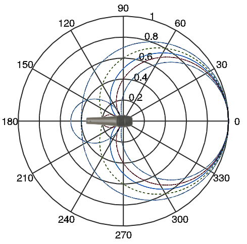
Above: A typical practical cardioid pattern. Each line represents the
pattern at a different frequency. Generally, the patterns that are more
toward the inside of the concentric pattern correspond to higher frequencies
and the patterns on the outside correspond to lower frequencies.
Illustration by Prof. dDB. The frequency sensitivity
of the Shure SM-58 cardioid microphone can be seen by clicking the next link
and scrolling about 3/4 of the way down the page to the "Typical Polar Pattern."
The sensitivity of the microphone's frequency response to direction means that
sounds picked up from the sides (especially) or the rear of the microphone
usually are not very high-fidelity. In the above plot notice that the pattern-lines
are fairly near each other and orderly (this is good) for angles up to about
60 degrees off-axis, but for angles more than about 120 degrees off-axis (up
to 180 degrees off-axis) the pattern gets further separated and some even
cross over the others (near angles around 150 degrees). These widely separated
and crossing lines will result in bad sound. As the microphone is turned away from
the source, before the sound fades it also starts to sound hollow and
distorted, especially for sounds coming in from the back of the microphone.
This dependency of the directional pattern on frequency is the
most serious disadvantage of a cardioid microphone. This video on
Directionality and
Proximity Effect will allow you to hear the hollow and distorted sound
that is picked up when the microphone is not aimed at the source of sound.
Listen with good headphones or earbuds at 1:35 to 1:45. Especially listen to
the sound of the actor's voice saying, "and I'm trying to maintain." In this
phrase, while the microphone is not quite pointed directly away from the
source of sound, the distortion is strong.
A minor disadvantage of a cardioid microphone is that it is more difficult to
miniaturize because the rear-ports (which give it directionality) need some
physical separation from the front of the microphone. But for a handheld or
stand-mounted microphone miniaturization is not needed, so this disadvantage
does not matter.
A third disadvantage of a cardioid microphone is that it is intrinsically a bit
more sensitive to plosives than an omnidirectional microphone, but it is not
as sensitive as a figure-of-eight microphone. Good wind screening can mitigate
this problem, but again at the expense of the size of the microphone since
good wind screening requires some space. Generally, wind screening of a cardioid
microphone is more important than for an omnidirectional microphone, and
not very hard to achieve.
The advantages of a cardioid microphone are several, but probably the main
advantage is that this microphone pattern just does what people naturally
expect a microphone to do. It picks up sound when it is aimed at the source
and not when it is aimed away from the source. All other microphone patterns
are harder for the general public to understand.
When it comes to preventing feedback, a cardioid microphone has a strong
advantage. If the loudspeaker(s) are placed in front of the sound sources, and if they
are aimed away from the microphones, then the cardiod pattern also helps
avoid picking up feedback. This arrangement usually provides very good
gain-before-feedback, even if the microphone might be only a few feet from
(but in back of) the loudspeakers. Also, if stage monitors (loudspeakers on the
floor aimed back at vocalists, guitarists, etc.) are used, cardioid microphones
can be aimed to avoid feedback from the monitor loudspeakers if the monitor
loudspeakers are placed several feet out in front of the vocalists, guitarists,
etc. (And not at the feet of the performer or behind the performer.)
Another advantage is that the proximity effect, so strong in figure-of-eight
microphones, is moderated in a cardioid pattern. This moderate proximity effect
is usually more pleasing than a strong proximity effect, and again, the general
public seems to naturally prefer about the amount of proximity effect that
a cardioid microphone typically has.
In a house-of-worship the disadvantages of a cardioid microphone (distortion of
off-axis sounds, difficult to miniaturize) are minor or even negligible. The
advantage of the intuitive directional pattern and the resulting feedback
reduction is huge. For this reason, most houses-of-worship use cardioid
microphones almost exclusively except for a few niche situations (primarily
lavalier and ear-set microphones that need miniaturization). All the microphones
at Covenant church are cardioid except the pastor's ear-set microphone (which
is omnidirectional).
 Super cardioid
- Picks up from directly in front, rejects from about 120°, some rear sensitivity.
- Can help reduce feedback problems when floor-wedge monitors are used.
- Proximity effect can be fairly strong
- Sounds entering from the rear or sides can be distorted.
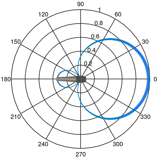
Above: The ideal super cardioid pattern. The numbers around the outside of the
plot show the angle, in degrees, from which a sound may arrive. The numbers between
0 and 1 on the radius to the right of 90 degrees label the fractional amount of sound
that might be picked up relative to an on-axis arrival. If you multiply this number
by 100 you get the percentage of sound that might be picked up relative to an on-axis
arrival. Maximum rejection of sound is at an angle of 120°. There is some pickup
of sounds arriving from the direct rearward end the microphone.
Illustration by Prof. dDB.
An exemplary application of a super cardioid microphone is a vocal microphone with a floor-wedge monitor speaker near the base of the microphone stand. There are two reasons why it is important to arrange the monitor speaker and microphone so that the microphone can reject the sound arriving from the monitor speaker. First, sound arriving from the rear of any microphone except an omnidirectional microphone is likely to be distorted and hollow sounding to the extent that the microphone picks it up. Secondly, if there is enough pickup from the monitor speaker feedback howl will ensue. In most cases a cardioid microphone can do an adequate job of rejecting sounds from floor-wedge monitors if the monitors are set five or six feet beyond the microphone stand toward the congregation. However, if the monitor can be brought closer to the vocalist it will not have to be driven as hard to make it adequately loud at the vocalist's ears. But as the monitor is moved closer to the microphone the angle of sound arrival encourages more sound to be picked up if a cardioid microphone is used. In contrast, if a super-cardioid microphone is used, then the monitor can be moved into a position closer to the angle of maximum rejection from the microphone. In a case such as illustrated below where the monitor speakers need to be close to the base of the microphone stand then a super cardioid microphone will be a better choice than a cardioid microphone.
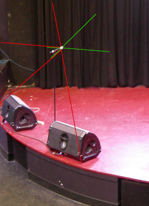
Above: A super cardioid microphone is used along with floor-wedge monitors.
The green lines illustrate the approximate angles of sensitivity. The red
lines illustrate the approximate angles of rejection. The monitors are placed
relative to the microphone to achieve strong rejection.
Wikimedia Commons (modified).
The reader might wonder why a super cardioid pattern is not generally better than
a cardioid pattern for house-of-worship situations. The philosophical answer is that
you should never expect a free lunch. Super cardioid microphones come with a set of
issues that are hard to work with. The angle of high-fidelity acceptance is usually
so narrow that most vocalists will not be able to completely stay within that desirable
angle, especially if the microphone is hand-held. The result will be that the tonal
quality of the sound will vary as the performer moves around. Additionally, the
proximity effect is usually more pronounced, giving the microphone a heavy sort of tone
whenever it is close to the sound source. In this video at 3:30 to
about 4:00 you can hear the typical sound of a super cardioid microphone including the
strong proximity effect and a slight variation in tonal quality as the microphone is
moved around. A performer using a super cardioid microphone needs to be aware of these
difficulties and needs to stay properly positioned relative to the microphone to get
good results.
Overall, for house-of-worship situations a super cardioid microphone may on occasion be
used to advantage, especially with regard to the use of floor-wedge monitors, but
in most situations a cardioid microphone will give more optimal results overall.
A microphone that is similar to a super cardioid is a hyper cardioid microphone.
One must really consult the manufacturer's specifications to see how far the cardioid
pattern has been compromised over toward that of a figure-of-eight since there is
no official standard for the pickup pattern of these microphones, but usually "hyper"
signifies that the microphone is closer to a figure-of-eight microphone with an angle
of maximum rejection of perhaps 100° to 110° whereas a super-cardioid microphone
is usually about a 33-67 compromise between a cardioid and a figure-of-eight pattern with
a maximum rejection angle of about 120°
 Shotgun and Parabolic Microphones
- Extra sensitivity for higher-pitched sounds arriving from directly in front.
- Main advantage is the ability to be placed far from the sound source.
- Low-frequency sounds entering from the rear or sides can be badly distorted.
- Consider rolling off low frequency sounds, using another mic to pick those up.
Be aware that for some people, and on some consumer-oriented Web pages, the phrase, "shotgun microphone" is used as a reference to a tubular or pencil-like shape for the microphone overall, not to the directional pattern of pickup. On these HoW Sound pages (and in the professional literature) the phrase "shotgun microphone" refers to the inclusion of an interference tube at the front of the microphone. Thus, for the purposes of this set of Web pages, not every pencil-shaped or tubular-shaped microphone is a "shotgun" microphone. Only those that have an interference tube are shotgun microphones.

Above: A typical shotgun or parabolic directional pattern, usually valid only for high
frequencies such as 2 kHz and up. Many variations with different numbers of lobes
and nulls are possible. Not shown: at low frequencies the pattern is more similar
to a supercardioid pattern. The numbers around the outside of the
plot show the angle, in degrees, from which a sound may arrive. The numbers between
0 and 1 on the radius to the right of 90 degrees label the fractional amount of sound
that might be picked up relative to an on-axis arrival. If you multiply this number
by 100 you get the percentage of sound that might be picked up relative to an on-axis
arrival.
Illustration by Prof. dDB.
I have arranged this discussion of directionality to show that as more sound is
admitted to the back side of the diaphragm of the capsule (via appropriate baffling
and/or labyrinths) the microphone becomes more directional (in the sense of
rejecting sound from the sides). But opening the back of the capsule
is not the only thing that can be done to create directionality. One can also
manipulate how the sound gets to the front of the capsule. This is the
technique of shotgun and parabolic microphones.
In a parabolic microphone usually an omnidirectional or cardioid basic design is
chosen for the capsule. To this, a parabolic reflector is added, and the front of
the capsule is placed at the focal point of the parabola and aimed into the parabola.
The back of the capsule is aimed toward the sound source. The parabola reflects
the sound into the front of the capsule. The large diameter of the parabola
relative to the capsule's diaphragm provides a type of acoustic amplification
resulting in the ability to pick up sounds far away from the parabolic reflector.
Sounds that arrive off-axis are also reflected by the parabola, but the off-axis
angle causes these sounds to be focused away from the capsule, so they are not
picked up very well. The parabola is not totally opaque to sounds arriving from
the back of the parabola, especially low-frequency sounds, so these sounds get
through to the front of the capsule. The result is that there is some
sensitivity to sounds arriving from the back of the parabola, especially low frequencies.
These sounds from the back side often sound hollow or boxy (as if emanating
from a box) due to their non-uniform frequency response.
In a shotgun microphone usually a supercardioid or occasionally a cardioid basic
capsule design is chosen. An interference tube is placed in front of the
capsule and is aimed at the sound source. The interference tube is a tube of
about the same diameter as the capsule's diaphragm and typically about a foot long.
It has carefully placed slots or holes or screens in it to allow a fraction of
the sounds arriving from off-axis to enter the tube and ricochet down the tube
finally arriving at the front of the capsule. When off-axis pressure waves
arrive at the diaphragm they are at random phases due to the variety of different
path lengths they have traveled down the interference tube. Thus, they cancel
each other out and the diaphragm does not respond well to them. Meanwhile,
on-axis sounds shoot coherently straight down the interference tube and do
not cancel each other out. A large amount of electronic amplification then
further extends the range of this frontal pick-up, and unfortunately simultaneously
amplifies the leakage into the signal of sounds from off-axis. This combination of
acoustic wave cancelation for off-axis sounds and electronic amplification
(of all the output of the capsule) narrows the angle of acceptance of
sound in the main lobe of the directional pattern and extends the distance
over which the microphone can pick up on-axis sound.
The above descriptions of how parabolic and shotgun microphones work may seem
convincing, but there is a problem. To be an effective reflector a parabola
needs to be at least a wavelength in diameter. An effective interference tube
needs to be at least a half-wavelength long. To put this in perspective consider
that the wavelength of a pipe-organ note is about twice the length
of the pipe (for a pipe that is open at the top). The wavelength of middle C
(also known as C4) is about four feet! (The organ pipe will be about
2 feet long.) So an effective parabolic reflector for this pitch would have
to be at least 4 feet in diameter and an effective interference tube would have
to be at least 2 feet long. Most parabolic and shotgun microphones are not
this big. This means that the highly directional character of parabolic and
shotgun microphones is typically limited to frequencies above 500 Hz or even
1000 Hz. (Above about the first or second C above middle C, C5
or C6.)
Obviously, a larger diameter parabola or a longer interference tube is better.
But such big microphones are unsightly and awkward. Compromises are made.
Most parabolic microphones are between one foot and three feet in diameter.
Most interference tubes are between 4 inches and 18 inches long. At the smaller
dimensions these microphones offer a pattern with a good enhancement of
directionality only at very high frequencies. Small parabolic and shotgun microphones
are successful in the marketplace mostly based on marketing hype and
uninformed customers or literally as toys.
On the other hand, an 18-inch-long
interference tube can be quite effective at frequencies above about 300 Hz, which
will include most human speech sounds. (Probably the longest shotgun microphone
ever made for commercial sale was the Electro-Voice model 643 at 7 feet long!)
For the spoken word, sibilant sounds (e.g. the hissy part of many "s" sounds) add much
to the ability to understand the speech and distinguish words like "sea" from "tea," "key," and "me."
The frequencies of these sibilant sounds are mostly above 1000 Hz and so a reasonably
large parabolic or shotgun microphone can be quite effective in picking these sounds up.
These microphones might not be natural sounding, but speech clarity is improved.
For musical vocals, excessive sibilance is distracting and un-musical sounding.
Using a parabolic or shotgun microphone can be even more complicated than the above
considerations might suggest. Making an interference tube that works effectively and
uniformly across a wide range of frequencies is challenging. In practice, the effectiveness
of the tube varies with frequency, even for frequencies for which the tube is long
enough to have an effect. Similarly, making a good parabolic reflector for sound that
does not itself vibrate with the sound (like a speaker cone) and thus distort the
reflection is difficult. Consequently, the directional pattern of parabolic and shotgun
microphone(s) vary a lot with frequency. The number of side-lobes in the pattern
and the number of nulls (angles from which sounds are practically eliminated)
changes as the frequency changes. This has the effect of making the off-axis sounds
that do manage to leak into the signal sound very low-fidelity. This low-fidelity sound
might be characterized as sounding muffled or nasally or screechy depending on the
angle of arrival. If the microphone or sound source are moving relative to each other,
these off-axis sounds can change character obnoxiously as time passes.
With all these limitations, you might be wondering how a parabolic or shotgun microphone
might be used to good advantage. The big advantage of these microphones is the
greater sensitivity of the front or main lobe of the directional pattern. The rejection
from the sides is not much of an advantage because they are not really as good at
rejecting from the sides as you might think. The distortion given to sounds that leak
through from the sides makes these sounds more prominent and obvious than desired.
In those rare cases where shotgun microphones are used in house-of-worship applications,
they are usually used in combination with other microphones. For example, one or two
shotgun microphones might be used to pick up congregational singing. Understanding
that the low-frequency sounds from these microphones might be poor-sounding, it is
common to severely roll off the low frequency sounds (say from 300 Hz on down) from
these shotgun microphones. To make up for this low-frequency roll off, some other
microphones such as some cardioid or omnidirectional microphones might be mixed in
to provide low-frequency support. Then the shotgun microphones support the
intelligibility of singing and the other microphones support the rhythm and bass
parts of the music. The resulting mix might not be true to the original sound in
the room, but it can have pleasing bass along with intelligible vocals. Sometimes,
when getting a microphone close to a choir is not practical, this same technique is
used for picking up a choir. In any case, getting a cardioid microphone or super-cardioid
microphone closer to the sound source is usually a better-sounding choice than resorting
to a shotgun microphone at a distance.
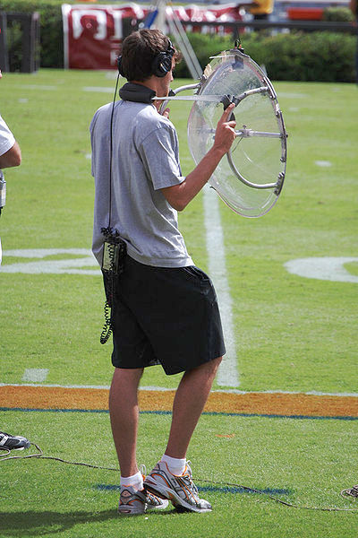
Above: A parbolic microphone in use at a football game.
Wikimedia Commons (modified).
There are applications where the advantages of parabolic and shotgun microphones really
shine. Parabolic microphones are often used to pick up field sounds in the televising of
sporting events. (The crack of the ball on a baseball bat, the sound of teams clashing
in football, etc.) In studio-based video recording work and in live news-gathering
events, such as a press conference, a shotgun microphone can be a good choice when
it is desired to keep the microphone outside of the video frame or when being able
to reach over a crowd is an advantage. Shotgun microphones are also occasionally
used in live theatre performances to unobtrusively pick up signals for
hearing-assistance systems. Shotgun microphones can be hidden above the stage or
in the wings of the stage. In these applications feedback is not possible so distorted
off-axis sounds are not as serious an issue, whereas in live sound relying on the
non-uniform directionality of a shotgun microphone is often a formula for feedback.
-320px.jpg)
Above: Shotgun microphones (both with additional windscreens) used for news
gathering.Wikimedia Commons
In good applications of shotgun and parabolic microphones getting intelligible
spoken-voice pickup (or other mid- and high-frequency sounds) from a microphone
that is far away from the sound source is the goal and the low-frequency sounds
are often rolled off because they sound ugly. Rejection of sounds from the
side and rear is not a strength of these microphones because distortion makes
these sounds more obvious and objectionable.
Because a shotgun microphone is highly directional it will be especially sensitive to
wind noise. Usually, a shotgun microphone is placed far from the person speaking so
plosives are not a problem, but if outdoors, a good windscreen is needed. Similarly,
the capsule of a parabolic microphone should be well windscreened when used outdoors.


 Directionality Summary
Microphones can be sensitive to either the absolute pressure vibrations in the
air that create sound, or they can be sensitive to the velocity of the air molecules
that are moving to create pressure vibrations and sound, or they can be sensitive to
some combination of both. Microphones sensitive to pressure variations only are
theoretically omnidirectional. Microphones sensitive to velocity variations only
theoretically have a figure-of-eight directional pattern, with the pickup from the
rear being out-of-phase compared to the pickup from the front. By using a combination
of pressure and velocity sensitivity the pickup pattern can be varied. In theory,
a 50-50 combination of pressure and velocity sensitivity gives a pattern called
cardioid. A 33% pressure, 67% velocity combination of pressure and velocity gives
a pattern called super cardioid. Microphones with 25%-75% combinations are
also available. Sometimes these are called hyper cardioid microphones. By adding
an interference tube or a parabolic dish in front of the capsule a super cardioid
or cardioid microphone can be made more directional yet, especially at high frequencies.
It is hard to keep the ratio of pressure and velocity sensitivity uniform across
all frequencies, and even harder to make an interference tube or parabolic dish
that acts uniformly
at all frequencies. This means that omnidirectional and figure-of-eight microphones
tend to give flatter frequency responses for off-axis arriving sounds. Other
microphones tend to not only attenuate sounds arriving from null angles, they
also tend to give these sounds arriving from near-null angles a hollow coloration,
sort of like an old telephone. Of course, some microphones have less coloration
of off-axis sounds than others.
Plosive sounds in vocals, such as "p,", "b," "s," and "t" sounds are not purely
from the vibrations and pressure waves of air. Some parts of these sounds are
from an explosive addition of air molecules emanating from the sound source.
Velocity-sensitive microphones are very sensitive to these sounds. In a
non-amplified environment people are not close enough to hear the
plosive content of plosive sounds, but a microphone held close to a plosive
source such as a vocalist might pick up these unpleasant sounds. Thus a velocity
sensitive microphone needs wind screening to attenuate plosive sounds. Although
this effect is especially strong with a velocity sensitive microphone, the
turbulence of airflow around a capsule can leave an omnidirectional microphone
with some slight sensitivity to plosives as well. For most speakers or
vocalists (except experienced professional vocalists) supplementary windscreening
around a microphone capsule is good
insurance that any near and prominent plosives get attenuated to normal proportions.
This is especially important with the more directional patterns; it is also
valid even for an omnidirectional microphone.
Close to a sound source the sound waves are curved. This makes no difference
for a pressure-sensitive microphone, but it does matter for a velocity sensitive
microphone. This gives every velocity-sensitive microphone a proximity effect.
A figure-of-eight microphone has a strong proximity effect because it is totally
velocity sensitive. The effect is so strong that usually all sources are kept
at least three or even six inches from the capsule. Omnidirectional microphones
have no proximity effect. That, in combination with a lack of coloration of
off-axis arriving sounds gives these microphones a natural advantage in
high-fidelity pickup. A little proximity effect tends to be flattering to most
vocals, both masculine and feminine. This, plus the intuitive notion that
the microphone ought to reject sounds from the rear, plus the feedback rejection
that results from a controlled use of the directionality of a microphone,
makes cardioid microphones the most popular overall choice for house-of-worship
microphone applications.
A demonstration of
microphone pick-up patterns can be found at
the video-link in this sentence. See especially the part from 7:30 to 9:10.
Listen to the hollow character of the sound of the voice when the sound is
arriving from an angle that should cause rejection. In addition to the
attenuation of the sound, the character of the sound is ugly when it arrives
off-axis. The microphone being demonstrated here is a very expensive and
high-quality model, yet this coloration is still audible. Also listen to the
room echo that the omnidirectional microphone picks up, and which is rejected
to varying degrees by the other patterns. This room-echo may be used to
very pleasing effect in a studio environment, but it is usually
out-of-control in a live-sound environment, mainly making feedback more
likely.
Directionality exists on a continuum from no directionality at all—that being
an omnidirectional pattern—to maximum directionality—a figure-of-eight
pattern and then beyond that, a parabolic or shotgun
pattern. By placing a labyrinth or a baffle at the back of the capsule's
diaphragm increasing sensitivity to velocity and decreased sensitivity to
pressure can be achieved and this adds directionality to the microphone's
pickup pattern. Adding an interference tube to the front of the capsule
further increases directionality. Omnidirectional
microphones are the easiest to miniaturize and the easiest to design for
high-fidelity. Highly directional microphones such as figure-of-eight
microphones and shotgun microphones tend to compromise fidelity or size and
weight or both.
3.) Audio Fidelity (vs. miniaturization and directionality)
Obviously, some microphones sound better than others. Can this be measured and
numerically quantified? Can this be qualitatively heard? Does a microphone
that measures best (using technical instruments and some sort of theory of what
is best) always qualitatively sound best to the listener? These matters are
debatable. Can a microphone make a vocalist or acoustic guitar or other acoustic
musical instrument sound better than the pure acoustic sound it makes? What do we
mean by saying, "make this guitar sound better?" There really are no definitive
answers to these questions. "Beauty is in the eye of the beholder," we say.
Or in this case, beautiful sound is in the ear of the listener.
On the other hand, the matter is not entirely a matter of undefinable qualitative
statements. If a microphone reviewer states that, "The XYZZY microphone, delivers
more top-end air, has a more liquid midrange, and has a tighter bottom end than
the Shure SM-58 microphone." does that help you understand which microphone to use?
The Shure SM-58 microphone is a de-facto industry standard in that it is a very
popular choice even when money is plentiful. But here is a statement that
in some particular circumstance the XYZZY microphone is a better choice than
the SM-58. How can we evaluate the truth of that statement? Only by experience.
To the question of which microphone sounds best for which application
there are some quantitatively definable concepts that are highly useful. Yet there
are also qualitative qualities that are hard to describe. Although both quantitative and
qualitative descriptions of microphones can be helpful, only quantitative descriptions
have general usefulness. Qualitative descriptions are always tied to the particular
application's context and the related equipment (mixer, windscreen, musical genre, etc.).
Thus, qualitative descriptions have a narrow range of validity, comparing only one
situation to a few others—qualitatively. Qualitative judgements mean the reviewer liked one total
situation more than another. If people judge the sound to be inferior
(a qualitative assessment) no degree of explaining technical specifications is
likely to sway that opinion. In spite of the generality of quantitative knowledge
about a microphone, we find that our choices always come down to qualitative judgements
which are validated mostly by the acceptance of others of our choices.
What is important in the end is the qualitative judgement of most listeners that
the sound is "good." But what is important in the beginning—in the design
or set-up phase of the live-sound reinforcement—is quantitative knowledge
of what technical specifications are needed to produce good sound.
For qualitative discussions about the use of microphones, one needs simply to
experience them in different contexts, even virtually, such as by perusing YouTube for
various comparisons and demonstrations of microphones. Then you need to make your own
decisions. Is, "more air," (or "tight bass" or "liquid midrange" or any similar qualitative
description) a good thing or a bad thing for the application you are contemplating?
Only a consensus of opinions of people who hear the result can decide. That is the
essence of a qualitative statement. What is "air" (or whatever) in the sound of a
microphone anyway? These terms seem to mean different things to different people,
but the use of such qualitative terms does not invalidate experience and comparisons.
To be of any general use, this discussion of "Audio Fidelity" will necessarily have to focus
on quantitative measurements of a microphone's characteristics. Specifically, frequency response,
dynamic range, and two types of distortion, harmonic and
intermodulation distortion.. The reader will find that understanding
these quantitative measures can give generally reliable suggestions on how the
microphones will qualitatively perform in various applications.
Before reading much further, you might find it helpful to watch one of the
many YouTube videos that have been published that qualitatively compare some
microphones. There are so many of these it is hard to pick a "best" video on
this topic, but here is one that will help give a surface-level qualitative
understanding of the nature of the difference between a poor (cheap) microphone
and a really good (expensive) one. The title of this video is:
$22 Microphone Vs. $3600 Microphone. This video compares four microphones,
the Newer NW-800 (~$22), the Shure SM-58 (~$100), the Shure SM-7 (~$400) and the
Neumann U-87 ($3600). (You will need good-quality ear-buds or headphones to
properly appreciate the video.)
![]() Frequency Response
Frequency Response
- Frequency response is best expressed as a graph.
- A flat horizontal line from 20 Hz to 20 kHz is the nominal ideal.
- The nominal ideal is usually compromised to achieve directionality, etc.
- If not a graph, then a frequency range with a decibel range is OK
Nominal ideal: 20 Hz–20 kHz ±0 dB
More typical example: 50 Hz–12 kHz ±4 dB - If not a graph and missing a decibel range, it is a weak specification
Example: 20 Hz–20 kHz (but how uniformly is this range is covered?) - Interpreting frequency response gives insight to the best ways to use the mic.
Human hearing is said to cover the range of frequencies from 20 Hz to 20 kHz. But just
as the sharpness of vision varies from person to person, so does the ability to hear
the full spectrum of sound from 20 Hz to 20 kHz. Most young children do come close
to being able to hear the full 20 Hz to 20 kHz spectrum, but even by the teenage years
most people start losing high-frequency and low-frequency response. Regardless, a goal
of a good sound reinforcement system should be to reinforce the full range of frequencies
from 20 Hz to 20 kHz.
With typical program material (spoken voice, music, but not test tones) a variation in
loudness of 3 dB is the smallest variation that will be reliably noticed by most people.
With training, smaller variations may be noticeable, but for practical purposes, frequency
response variations between two microphones of less than 3 dB are insignificant unless the
sounds are carefully compared. Variations between 3 and 6 dB are noticeable, but still not
objectionable to some listeners. Variations of 10 dB or more are usually obnoxious. However,
if the source does not contain frequencies where the variations are the greatest, even
20 dB variations in the frequency response can go unnoticed.
Of course, no real microphone has a perfectly flat frequency response. The diaphragm of the capsule
of a microphone has mass, damping, and elasticity to some degree so there are always resonances
in even the most expensive microphones. The frequency response of any real microphone will depart
from the ideal. (This is also true for the cone of a loudspeaker, the stylus of a phonograph, etc.)
On the other hand, modern electronics are easily made to have quite ideal frequency responses.
The mixer board and the power amplifier and any electronics like these have, for all practical
purposes, ideal frequency responses (given professional level equipment). Thus, in a
house-of-worship situation the choice of microphones is usually the single most influential
factor in the overall frequency response of the sound system.
Suppose a microphone has almost no output below 50 Hz as shown by the frequency response.
Then no amount of equalization will be able to accurately create the bass sounds that the
microphone did not pick up in the first place. It is essential that the microphone
has a reasonable response at the frequencies that it will need to pick up. But that said,
small frequency response variations can often be practically corrected by using the
equalizer of the mixer's channel strip.
Most microphones' frequency responses are optimized for particular purposes.
Vocal microphones, for example, typically have a frequency response that avoids any loss
of frequencies in the range of 2 kHz to 6 kHz because these frequencies are very important
to the understandability and clarity of speech. Simultaneously, if the microphone is designed
to be hand-held, it often rolls down the low frequency response because human voices, even the
deepest bass voice, have little content below 80 Hz while the noise of the
microphone wire flopping around and fingers moving on the microphone's body are mostly below
80 Hz. Thus, for clear vocals, a good choice is a microphone that suppress frequencies below
80 Hz and enhances the 2 kHz to 6 kHz frequency range by a few decibels. The Shure SM-58 microphone
has been a big success in the marketplace, and it has such a frequency response. This is
strong evidence that this type of frequency response is desirable for vocals. Even if it is
not perfectly flat, it performs well at the frequencies of vocals and rejects handling noise.
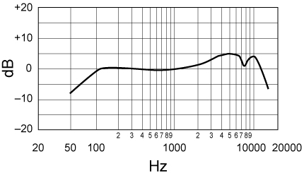
Above: Frequency response of a Shure SM-58 microphone, popular for vocals. Note the
approximately 5 dB rise at frequencies from 2 to 6 kHz (2000 to 6000 Hz). Also note the
low-frequency roll-off (below 100 Hz) to suppress handling noise.
(Graph is from the Shure SM-58 User's Manual. Fair use.)
For an instrument microphone the first priority is usually a flat low-frequency response from about 80 Hz down as close to 20 Hz as possible. Instrument microphones with good low frequency response and a slight emphasis of high frequencies of about +3 dB from about 4 kHz and up as high as possible (to perhaps 20 kHz) tend to be popular. Comparing to a vocal microphone, the low frequency response is flatter and the boost in high frequencies, if any, is less in amplitude and happens at higher frequencies.
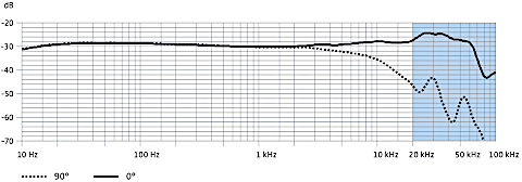
Above: Frequency response of a typical instrument microphone (Sennheiser MKH8020). Note the
nearly flat response down past 20 Hz and the slight rise above 4 kHz. (Everything above
20 kHz is inaudible because it is supersonic.)
(Graph is from the Sennheiser MKH8020 User's Manual. Fair use.)
A reference microphone (also known as a measurement microphone) is designed to have as flat of a frequency response as the manufacturer can manage. Since all other aspects of the microphone may be compromised to achieve this flatness, these are usually not good choices for live sound reinforcement. Reference microphones tend to be omnidirectional, have a high noise floor, and have a low dynamic range. The intended application of a reference microphone is for spectrum analysis and setup of room equalization and similar technical purposes. Other than that there are almost always better choices of microphones for live-sound applications in houses-of-worship. A typical example of a reference microphone is the Earthworks M50.

Above: Frequency response of a typical reference microphone (Earthworks M50). Note the
ruler-flat response down past 20 Hz and even above 20 kHz.
(Everything above
20 kHz is inaudible because it is supersonic.)
(Graph is from the Earthworks M50 User's Manual. Fair use.)
General-purpose studio microphones offer switches and sometimes interchangeable capsules
and other accessories to tailor the frequency response and/or the directionality to
different situations. The AKG C414XLS, Neumann U87Ai, and Shure SM-81, are examples. Most of these
can be configured as vocal or instrument or reference microphones depending on how they are set up.
Many of these types of microphones are impractical for live-sound use, mainly due to the complexity
of setting them up advantageously for various situations. On the other hand, if you set up such
a microphone more-or-less permanently for a dedicated purpose, they might be useful. An example
would be a stereo pair used to mic a grand piano and always used in the same setup and positions.
In a situation like that the sound operators do not need to spend time at each event considering
the switch settings on the microphones and carefully searching for the best positions for them for
each event. The technique can be the same at each event.
General-purpose studio microphones are mentioned here just to let you know that they exist and
in case there is a particular application you have for them, but usually other microphones are
going to routinely be more cost effective.
Some consumer-grade microphones have similar switching options to general-purpose studio
microphones, but the overall quality is not in the same league. Their lower cost makes them
popular for karaoke, podcasting, teleconferencing, and similar applications. A popular example of a
consumer-grade general-purpose microphone is the Blue Yeti and its many variations.
(The frequency response of any of the Blue Yeti models is nowhere near as flat as professional
microphones can provide.) Usually, consumer-grade microphones are not good choices for live-sound
house-of-worship applications even though they are great choices for their target applications.
 Dynamic Range
- For every mic there is a maximum sound-pressure level (in dB-SPL) that it can
accept without undue distortion.
- Every microphone generates slight self-noise. In the microphone's output,
self-noise typically has a hissing or whooshing sound, as if it is something
like wind, very soft. Others might describe it as the sound of brushing
your hand through some long grass. - The difference between the maximum acceptable SPL and the equivalent SPL of
the self noise is the microphone's dynamic range. - Sounds to be picked up by the microphone must have a loudness that fits well
in the microphone's dynamic range.
Recall that about 191 dB-SPL is the highest sound pressure level that is possible in a normal atmosphere
and that 120 db-SPL is the threshold of pain (borderline discomfort). A microphone placed inside a kick
drum might experience 150 dB-SPL. A microphone held up close to the lips of a person shouting as loud as
possible might experience 130 dB-SPL. It is important that the microphone you choose can handle the loudest
sounds. Most microphones have a maximum loudness limit that increases as frequency increases. Thus, a kick
drum (lots of low frequency content) is a challenge for a microphone with a limited maximum SPL, but
most other types of sources have such little low-frequency content that they are handled easily.
Some older (pre-1970's) models of condenser microphones had relatively low maximum SPL capabilities.
Because of this, condenser microphones have developed a reputation of being unsuitable for loud sound
sources such as drums and trumpets and even a loud vocalist. But this reputation is outdated now.
Most modern condenser microphones, some very inexpensive ones excepted, have maximum SPL capabilities
approaching those of popular dynamic microphones such as the Shure SM-58. Consequently maximum SPL capability
is usually only an issue for drums and possibly trumpets, and then only if the microphone is very
close to the instrument. For house-of-worship applications a maximum SPL capability of 125 dB or
more should be enough, except for close-miking of drums when 140 dB-SPL or more would be better.
On the soft side of the dynamic range issue, every microphone generates some slight amount of self-noise.
This self noise is created by the thermal motion of atoms of the atmosphere bouncing off the diaphragm.
In addition, any preamplifier in the microphone will generate more self-noise due to thermal motion
of electrons and other causes in the electronics. You can notice self-noise if you place the microphone
in a quiet place (e.g. muffled tightly between pillows in a quiet room) and then, using headphones and
with all loudspeakers turned off (so there can be no feedback) turn up the volume really high. You will
hear a hissing sound. Some of this hiss is from the microphone itself. (Some more of it may be from the
console you are using.)
If the sound you are attempting to pick up with the microphone is not
loud enough, it cannot overcome the self-noise of the microphone. For example, if the sound you want to
pick up is at a level of 55 dB-SPL and you want at least a 30 dB signal-to-noise ratio, then your microphone
must have a self-noise level of 55 – 30 = 25 dB-SPL. Otherwise, when the sound is soft you
will hear the hiss of the microphone's self-noise in the background. As you can imagine, the need to pick
up such soft sounds is rarely a problem in a house-of-worship situation. If you hear hiss or think you are
having a problem with a microphone's self-noise, check the gain trim on that channel first. Gain structure errors are more common and can produce hiss that sounds just like microphone self-noise.
Microphone self-noise is measured in comparison to a theoretically perfect microphone which has no self-noise
at all. Imagine two rooms. One is perfectly silent--an anechoic chamber with no sound source in it.
Put the microphone to be tested in this room. Measure the loudness of the signal that comes from the
microphone. Since there is no acoustic signal in this room, all the signal from this microphone is
self noise. Now in the second room--also an anechoic chamber--place an ideal noise-free microphone and
also a source of "A weighted" (or CCIT weighted) noise. (This sounds hissy, like radio static between stations.) Turn up the level of the noise until the signal from the ideal microphone matches the
strength of the signal from the microphone being tested. Measure, in dB-SPL, the loudness in the room that has
the noise source. This is the level of self-noise in the microphone being tested. (Of course, there is no
such ideal microphone to use for this test, so an actual test requires use of a calibrated and well-understood
microphone with very low self-noise and some math to compensate for the self-noise of the nearly ideal
microphone.)
Because self-noise is usually not an issue with a dynamic microphone, most specification sheets for
dynamic microphones don't mention anything about it. Better condenser microphones will include self-noise
on their specification sheets. For house-of-worship applications anything below about 25 dB-SPL
A weighted is good enough. (Or anything below about 37 dB SPL CCIT weighted.)
Hum
Technically, hum is not self-noise. But this seems to be an appropriate place to discuss it. If you
are having trouble with hum, the first thing to check is the microphone cable. A broken wire in the
cable can reduce the cable's ability to shield the signal from hum. But aside from a defect like that,
dynamic microphones are inherently slightly suceptible to hum pickup from
nearby magnetic fields such as flourescent light balasts, motors, and sometimes just the wiring in the
walls. Most dynamic microphones are designed assuming the microphone is used in a place free of stray
magnetic fields (other than the Earth's natural magnetic field, which is not a problem anyway).
Higher-quality dynamic microphones include a hum bucking coil to almost completely eliminate
the slight suceptibility to stray magnetic fields. If a humbucking coil is present the microphone
can be expected to have very little or no audible hum in its output in practically every circumstance.
Humbucking coils are also known as compensating coils—same thing. Condenser microphones
never include humbucking coils because they are insensitive to magnetic fields in the first place.
If a microphone includes a humbucking coil you can expect it to be mentioned in the user's manual
or on the specifications sheet. If it does not include a humbucking coil usually there is no
mention made of this omission. The popular Shure SM-58 and the AKG D5 are microphones that are
susceptible to magnetic fields. The Electrovoice RE-20 and the Shure SM-7 are examples of
microphones with hum-bucking coils.
In summary, the microphone you choose needs to have enough dynmaic range to accomodate the sound
source. This means the maximum SPL specification of the mic must be greater than the maximum loudness
of the sound or you will hear clipping distortion. The self-noise of the microphone must be many decibels (30dB or more) below the minimum
loudness of the sound or you will hear hiss. A dynamic microphones without humbucking coil might have a slight hum in the
background of the sound, meaning it should not be used for soft or delicate sounds. The DPA
Microphone company has a good summary video: "Understanding dynamic range and the sound pressure level of the voice." Their video puts
emphasis on the maximum SPL issue. Lewitt company also has a good video on this topic, this time
with the emphasis on the self-noise issue. "Learn WHY Microphone Self-Noise matters."
![]() Distortion
Distortion
- Professional audio equipment, when properly applied, installed and adjusted,
has been free of noticeable distortion issues since at least the 1950s. - If a microphone distorts the signal, it is usually because the acoustic source is
too loud. (dB-SPL is above the microphone's maximum rating) - Other reasons for microphone distortion include water or dirt infiltration.
- One measure of audio fidelity is total harmonic distortion or THD
(lower is better, less than 1% is good—the distortion will be inaudible.) - Another measure of audio fidelity is intermodulation distortion.
- Clipping is still another type of distortion.
Total Harmonic Distortion (THD)
A microphone is supposed to covert air pressure variations plus air velocity variations into a
voltage signal. Ideally, a doubling of air pressure variation should cause a doubling of
voltage and similarly, a doubling of air velocity should cause a doubling of voltage. It
does not have to be a doubling either. If one triples, the other should triple.
Mathematically, the ideal distortion free response of a microphone is
v(t) = Sp1p(t) + Sw2w(t)
Where:
Sp1 = Pressure sensitivity transfer factor (V/Pa)
p(t) = Air pressure variation as a function of time
Sw1 = Air velocity variation sensitivity transfer factor (Vs/m)
w(t) = Velocity variation as a function of time
[Sidenote: The amount of directionality is d = Sw1/(Sw1 + Sw1)
Thus, if d ≠ 1 one has v(t) = Sp1[1/(1 - d)]p(t)
Where Sp1[1/(1 - d)] is the overall sensitivity of the microphone (in V/Pa).
For omnidirectional, d = 0;
cardioid, d = 0.5;
supercardioid, d ≈ 0.66;
bidirectional, d =1]
Using physics one can show that the velocity variation is always proportional to the pressure variation (for non-plosive sounds). Thus if the pressure variation doubles (or changes by any factor) then the velocity variation also doubles (or changes by the same factor). Then, in the equation for v(t) notice that if p(t) doubles (or changes by any factor) then v(t) doubles as well (or changes by the same factor. This is ideal distortion-free behavior. For this to happen the diaphragm must move proportionally with the pressure variations in the air
Now let us consider a situation that creates distortion. Suppose that either or both of the sensitivity transfer factors vary with the position of the microphone's diaphragm. Maybe as the diaphragm moves farther from the rest position the sensitivity factors decline just a bit. Now if the pressure variations double the voltage generated will not quite double. This is nonlinear behavior. This is distortion. How can this be measured?
There are no totally comprehensive ways to measure distortion because there are so many ways that distortion may be created. However, Total Harmonic Distortion Plus Noise (THD+N) has been found to be a generally useful way to characterize distortion. To make this measurement one puts the microphone in the sound-field of a pure tone, such as might be created by a tuning fork of a particular pitch or frequency. Then filters out, from the voltage signal, anything having that pitch or frequency, leaving all the rest of the signal. If the microphone produces a distortion-free output, then there will be nothing left at the output of the filter because there were no sounds that could make it through the filter in the acoustic sound that entered the microphone. The THD+N is defined as the power of the signal at the output of the filter divided by the power of the signal entering the filter. That will be a fraction between 0 and 1. Multiply by 100% and you get the THD+N as a percentage, which is the way it is usually expressed.
In applications typical of a house-of-worship, the amount of noise delivered by a microphone is so minuscule relative to the fundamental sound used for testing THD+N that noise is entirely negligible when measuring THD+N. There is a more sophisticated measure called just Total Harmonic Distortion (THD). This requires a filter that rejects the fundamental sound but also any sounds that are not harmonically related to the fundamental sound (e.g. noise). Thus, a true THD measurement requires this more sophisticated filter. But in practice, THD+N is usually measured and then reported as simply THD. Even though this is a short-cut way of measuring THD, in every practical way this is an accurate measurement of THD for any microphone, amplifier, loudspeaker, or other audio component. Only in sophisticated laboratory situations would one ever notice the difference between THD+N and THD. For our purposes, they are essentially the same thing.
Clipping
Clipping is an extreme type of distortion. Suppose the sound-pressure-level of the sound presented to a microphone is so intense as to move the diaphragm all the way to the limits of its motion, and would move the diaphragm further if it could. When the diaphragm hits its limit, that will induce a sound into the signal that is not present in the acoustic sound. (When the suspension of a car hits its limit you might hear a clunking sound. Similarly when a diaphragm hits its limit.) Furthermore, that "clipping" sound will be harmonically related to the fundamental acoustic sound. (If the sound changes pitch, the clipping distortion will also change pitch, thus a harmonic relationship.) Clipping creates THD when the sound is loud enough.
Intermodulation Distortion (IMD) THD is measured with a pure tone of a specific frequency. When there is more than one tone, for example two tones, one of 400 Hz and one of 1000 Hz then of course an undistorted signal will have only those two tones in it. However, distortion can cause the sum and difference frequencies, 1400 Hz and 600 Hz in this example, to become audible. Intermodulation distortion is measured similarly to THD, but now the filter rejects all signals except the sum and difference frequencies of the two tones applied. Intermodulation distortion is then the fraction or percentage that the power at the output of the filter is in comparison to the power at the input of the filter. Like THD, the signal itself has a strong tendance to mask the intermodulation distortion, so intermodulation distortion less than 1% is inaudible. Non-zero THD is necessary for any intermodulation distortion to exist. If THD is less than 1% then intermodulation distortion is almost certain to be negligible.
In power-amplifier and loudspeaker applications, the reduction of intermodulation distortion is a primary advantage of using active crossovers and separate power amplifiers ("Bi-amping"). By separating the audio into various frequency bands each amplifier/speaker pathway deals with fewer frequencies, therefore each creates less intermodulation distortion such that the sum of all pathways has much less intermodulation distortion than otherwise.
Summary of the topic of distortion
Because fundamental sound is so much stronger than the harmonic distortion (plus noise if appliable) the fundamental has a strong ability to mask the distortion. If the total harmonic distortion is under 3% in most situations hardly anyone (if anyone) will notice it. Distortion levels of up to 10% might go unnoticed by the general public. You can judge for yourself in this video: "How much distortion can you hear?" In electronic circuits (mixing console, amplifiers, etc.) distortion levels well below 0.1% are routine unless there are significant issues such as clipping or low supply voltage (weak batteries), or gain structure issues, etc. In professional-grade microphones and loudspeakers distortion levels under 1% are also routine. (Example: The Shure SM-94 microphone, a microphone noted for low distortion, is specified to have less than 0.25% total harmonic distortion.) Even though transducers may introduce an order of magnitude more distortion into the system than the electronics does, the amount is well below an audible level. Harmonic distortion should never be a problem.
Frequency response specifications may be helpful in understanding if the microphone will be a good fit to a particular application. For spoken word and vocal music a smooth response that is between 0 and +5 dB between 100 Hz and 8 kHz, with perhaps some emphasis in the 3 to 5 kHz range seems to give pleasing results. For musical instruments, flat response overall and especially between 100 Hz and 40 Hz for bass instruments tends to give pleasing results. (Flat frequency response extending to 20 Hz is still better, but extending to 40 Hz brings most of the benefit.) If there is emphasis of frequencies it is best if it is less than +3 dB relative to 1000 Hz. Overall smoothness and flatness of the curve is desirable for picking up musical instruments. In the final analysis, the microphone that you have on hand that sounds best in the application is the one to use.
When it comes to microphones, hum, self-noise (hissing), and clipping (lack of dynamic range), are all problems that have well-known solutions. While these problems may occasionally present themselves, they should never be an insurmountable issue in a church sound system.
To be continued. . .
Planned for the future on this page:
--Capsule technologies
* dynamic
* condenser
* electret
* piezoelectric, a.k.a. crystal
* ribbon
* carbon
* fiber-optic
* laser
* MEMS
* Plasma
* "Speaker in reverse" (kick drum mic)
Planned for the future on another page:
-Techniques for using microphones
Return to HoW Sound homepage